


ST
ART
HERE
This
c
hapter
con
tains
follo
wing
troublsho
oting
pro cedures.
By
p erforming
them
in
the
order
listed
b elow,
y
ou
can
iden
tify
the
faulty
assem
bly
or
the
faulty
group
ecien
tly
.
1.
Disconnect
ev
erything
from
the
analyzer:
All
test
set
in
terconnect,
GPIB
cable,
prob e
p o
w
er,
and
RF
cables.
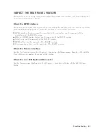
2.
P
erform
the
INSPECT
THE
PO
WER-ON
SEQUENCE
in
this
c
hapter.
3.
P
erform
the
INSPECT
THE
REAR
P
ANEL
FEA
TURE
in
this
c
hapter.
4.
P
erform
the
INTERNAL
TESTS
F
AILURE
TR
OUBLESHOOTING
in
this
c
hapter.
5.
P
erform
the
EXTERNAL
TESTS
F
AILURE
TR
OUBLESHOOTING
in
this
c
hapter.
6.
P
erform
the
p erformance
tests
in
the
Performanc
e
T
est
c
hapter
and
refer
to
PERFORMANCE
TEST
F
AILURE
TR
OUBLESHOOTING
in
this
c
hapter.
If
the
analyzer
has
passed
all
of
the
c
hec
ks
but
it
still
making
incorrect
measuremen
ts
or
unexpected
op erations,
susp ect
the
accessories.
Accessories
suc
h
as
RF
or
in
terconnect
cables,
calibration
and
v
erication
kit
devices,
test
set
can
all
induce
system
problems.
Congure
the
system
as
it
is
normally
used
and
reconrm
the
problem.
Con
tinue
with
the
A
c
c
essories
T
r
oublesho
oting
c
hapter.
Troubleshooting
6-3
Summary of Contents for 4395A
Page 10: ......
Page 26: ......
Page 34: ......
Page 77: ...Figure 2 17 B R Magnitude Ratio Phase Dynamic Accuracy Test Setup 2 Performance Tests 2 43 ...
Page 167: ...Figure 5 1 Adjustment Hardware Setup Adjustments 5 5 ...
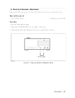
Page 186: ...Figure 5 13 Receiver Gain Adjustment Location 5 24 Adjustments ...
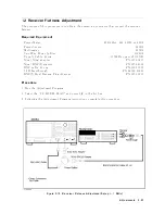
Page 190: ...Figure 5 16 Receiver Flatness Adjustment Setup 1 MHz 5 28 Adjustments ...
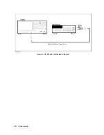
Page 194: ...Figure 5 20 DC Bias Adjustment Setup 2 5 32 Adjustments ...
Page 196: ...Figure 6 1 Troubleshooting Organization 6 2 Troubleshooting ...
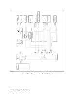
Page 206: ...Figure 7 1 Power Supply Lines Simplified Block Diagram 7 2 Power Supply Troubleshooting ...
Page 212: ...Figure 7 5 A1 CPU Connector Locations 7 8 Power Supply Troubleshooting ...
Page 220: ...Figure 8 1 Digital Control Group Simplified Block Diagram 8 2 Digital Control Troubleshooting ...
Page 240: ...Figure 10 1 Top View Major Assemblies 10 4 Replaceable Parts ...
Page 292: ...Table A 2 Manual Changes by Firmware Version Version Make Manual Changes A 2 Manual Changes ...
Page 308: ......
Page 311: ...Figure B 1 Power Cable Supplied Power Requirement B 3 ...
Page 312: ......
Page 342: ......


