


FIRMW
ARE
INST
ALLA
TION
No
rm
w
are
is
installed
in
new
A1
CPU
assem
bly
.
When
y
ou
replace
a
faulty
A1
CPU
with
a
new
one,
p erform
the
following
steps
to
install
the
rm
w
are
in
to
the
A1
CPU.
Ordering
the
Firmw
are
Disk
ette
A
rm
w
are
disk
ette
(3.5
inc
h)
that
con
tains
the
analyzer's
rm
w
are
is
required
for
the
rm
w
are
installation.
If
y
ou
do
not
ha
v
e
a
rm
w
are
disk
ette,
y
ou
m
ust
order
one.
F
or
ordering
information,
con
tact
y
our
nearest
Agilent
T
ec
hnologies
service
cen
ter
and
pro
vide
the
revision
of
the
analyzer's
rm
w
are.
The
part
n
um
b er
of
the
rm
w
are
disk
ette
dep ends
on
the
rm
w
are
revision.
The
rm
w
are
revision
of
the
analyzer
is
indicated
on
the
revision
lab
el
attached
on
the
rear
panel
as
sho
wn
in
Figure
8-3 .
Figure
8-3.
Firmw
are
Revision
Label
Installing
the
Firmw
are
P
erform
the
following
pro cedure
to
install
the
rm
w
are
in
to
the
analyzer.
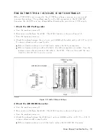
1.
T
urn
the
analyzer
p o
w
er
o.
2.
Press
b oth
the
4
Start
5
and
4
Preset
5
k
eys.
While
pressing
b oth
k
eys,
turn
the
analyzer
p o
w
er
on.
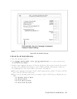
3.
W
ait
un
til
the
b o otloader
men
u
app ears
on
the
LCD
as
sho
wn
in
Figure
8-4.
8-4
Digital
Control
Troubleshooting
Summary of Contents for 4395A
Page 10: ......
Page 26: ......
Page 34: ......
Page 77: ...Figure 2 17 B R Magnitude Ratio Phase Dynamic Accuracy Test Setup 2 Performance Tests 2 43 ...
Page 167: ...Figure 5 1 Adjustment Hardware Setup Adjustments 5 5 ...
Page 186: ...Figure 5 13 Receiver Gain Adjustment Location 5 24 Adjustments ...
Page 190: ...Figure 5 16 Receiver Flatness Adjustment Setup 1 MHz 5 28 Adjustments ...
Page 194: ...Figure 5 20 DC Bias Adjustment Setup 2 5 32 Adjustments ...
Page 196: ...Figure 6 1 Troubleshooting Organization 6 2 Troubleshooting ...
Page 206: ...Figure 7 1 Power Supply Lines Simplified Block Diagram 7 2 Power Supply Troubleshooting ...
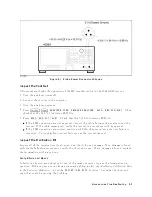
Page 212: ...Figure 7 5 A1 CPU Connector Locations 7 8 Power Supply Troubleshooting ...
Page 220: ...Figure 8 1 Digital Control Group Simplified Block Diagram 8 2 Digital Control Troubleshooting ...
Page 240: ...Figure 10 1 Top View Major Assemblies 10 4 Replaceable Parts ...
Page 292: ...Table A 2 Manual Changes by Firmware Version Version Make Manual Changes A 2 Manual Changes ...
Page 308: ......
Page 311: ...Figure B 1 Power Cable Supplied Power Requirement B 3 ...
Page 312: ......
Page 342: ......


