

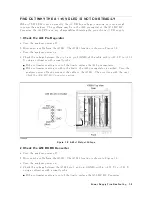


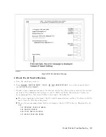


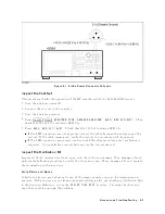


Figure
8-5.
A1
Eight
LEDs'
P
attern
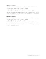
2.
Check
Error
Messages
T
urn
the
analyzer
p o
w
er
on.
Chec
k
no
error
message
app ears
on
the
LCD.
If
no
error
message
is
display
ed,
con
tinue
with
the
Che
ck
A1
DRAM
and
Flash
Memory
in
this
ST
AR
T
HERE.
If
one
of
error
messages
listed
b elow
is
display
ed,
follo w
the
instruction
describ ed
b elow.
F
or
the
other
message,
see
the
Err
or
Messages
in
Messages.
Error
Messages
Instruction
POWER
ON
TEST
FAILED
This
indicates
the
p o
w
er
on
selftest
failed.
Con
tinue
with
the
next
Che
ck
Power
On
Selftest
in
the
c
hapter
6.
EEPROM
CHECK
SUM
ERROR
This
indicates
that
the
correction
constan
ts
stored
in
the
EEPR
OM
on
the
A1
CPU
are
in
v
alid
or
the
EEPR
OM
is
faulty
.
Rewrite
all
correction
constan
ts
in
to
the
EEPR
OM.
F
or
the
detailed
pro cedure,
See
the
A
djustments
c
hapter
in
this
man
ual.
If
the
rewriting
is
not
successfully
p erformed,
replace
the
EEPR
OM
and
then
rewrite
the
all
correction
constan
ts
in
to
the
new
EEPR
OM.
Svc
(Status
Annotation)
This
indicates
that
the
correction
constan
ts
stored
in
the
EEPR
OM
on
the
A1
CPU
are
in
v
alid
or
the
EEPR
OM
is
faulty
.
See
the
instruction
of
the
EEPROM
CHECK
SUM
ERROR
message.
POWER
FAILED
ON
-
-
-
One
or
some
of
A2
p o
w
er
supplies,
+15
V,
+8.5
V,
+5.3
V,
+5
V,
-5
V,
-15
V
are
display
ed
in
-
-
-
of
the
message.
The
display
ed
p o
w
er
supplies
are
sh
ut
do
wn
due
to
the
trouble
on
the
A2
p ost-regulator.
Con
tinue
with
the
Power
Supply
T
r
oublesho
oting
c
hapter.
Digital
Control
Troubleshooting
8-7
Summary of Contents for 4395A
Page 10: ......
Page 26: ......
Page 34: ......
Page 77: ...Figure 2 17 B R Magnitude Ratio Phase Dynamic Accuracy Test Setup 2 Performance Tests 2 43 ...
Page 167: ...Figure 5 1 Adjustment Hardware Setup Adjustments 5 5 ...
Page 186: ...Figure 5 13 Receiver Gain Adjustment Location 5 24 Adjustments ...
Page 190: ...Figure 5 16 Receiver Flatness Adjustment Setup 1 MHz 5 28 Adjustments ...
Page 194: ...Figure 5 20 DC Bias Adjustment Setup 2 5 32 Adjustments ...
Page 196: ...Figure 6 1 Troubleshooting Organization 6 2 Troubleshooting ...
Page 206: ...Figure 7 1 Power Supply Lines Simplified Block Diagram 7 2 Power Supply Troubleshooting ...
Page 212: ...Figure 7 5 A1 CPU Connector Locations 7 8 Power Supply Troubleshooting ...
Page 220: ...Figure 8 1 Digital Control Group Simplified Block Diagram 8 2 Digital Control Troubleshooting ...
Page 240: ...Figure 10 1 Top View Major Assemblies 10 4 Replaceable Parts ...
Page 292: ...Table A 2 Manual Changes by Firmware Version Version Make Manual Changes A 2 Manual Changes ...
Page 308: ......
Page 311: ...Figure B 1 Power Cable Supplied Power Requirement B 3 ...
Page 312: ......
Page 342: ......


