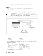


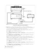


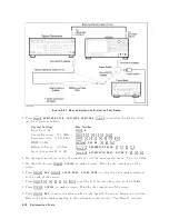


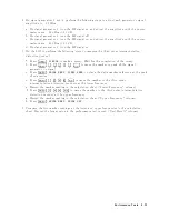


Figure
2-25.
Frequency
Response
T
est
Setup
2
m.
Rep
eat
steps
1-g
through
1-k
to
remov
e
the
p o
w
er
splitter
tracking
c
haracteristic.
Record
the
4395A
marker
reading
and
p o
w
er
meter
reading
in
the
in
\ 4395A
Reading
2"
and
\P
o
w
er
Meter
Reading
2"
columns
of
the
calculation
sheet.
n.
Remo
v
e
the
p o
w
er
splitter
from
the
R
input,
and
connect
it
directly
to
the
A
input.
o.
Press
4
Meas
5,
NNNNN
A
to
set
the
4395A
to
the
A
input.
p.
Press
4
Scale
Ref
5,
NNNNNNNNNNNNNNNNNNNNNNNNNNNNNNNNNNNNNNNNNNNNNNN
ATTENUATOR
MENU
,
NNNNNNNNNNNNNNNNNNNNNNN
ATTEN
A
,
4
1
5,
4
0
5,
4
x1
5
to
set
the
input
attenuator
to
10
dB.
q.
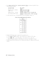
Press
4
Bw/Avg
5,
NNNNNNNNNNNNNNNNNNNN
RES
BW
,
4
3
5,
4
0
5,
4
0
5,
4
k/m
5
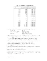
in
the
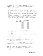
rst
column
of
T
able
2-22.
T
able
2-22
lists
the
test
settings
at
frequencies
1
MHz.
r.
Rep
eat
steps
1-h
through
1-m
to
remov
e
the
p o
w
er
splitter
tracking
c
haracteristic.
Record
the
4395A
marker
reading
and
p o
w
er
meter
reading
in
the
in
\ 4395A
Reading
2"
and
\P
o
w
er
Meter
Reading
2"
columns
of
the
calculation
sheet.
s.
Remo
v
e
the
p o
w
er
splitter
from
the
A
input,
and
connect
it
directly
to
the
B
input.
t.
Press
4
Meas
5,
NNNNN
B
to
set
the
4395A
to
the
B
input.
u.
Press
4
Scale
Ref
5,
NNNNNNNNNNNNNNNNNNNNNNNNNNNNNNNNNNNNNNNNNNNNNNN
ATTENUATOR
MENU
,
NNNNNNNNNNNNNNNNNNNNNNN
ATTEN
B
,
4
1
5,
4
0
5,
4
x1
5
to
set
the
input
attenuator
to
10
dB.
v.
Press
4
Bw/Avg
5,
NNNNNNNNNNNNNNNNNNNN
RES
BW
,
4
3
5,
4
0
5,
4
0
5,
4
k/m
5
in
the
rst
column
of
T
able
2-22.
T
able
2-22
lists
the
test
settings
at
frequencies
1
MHz.
2-68
P
erformance
T
ests
Summary of Contents for 4395A
Page 10: ......
Page 26: ......
Page 34: ......
Page 77: ...Figure 2 17 B R Magnitude Ratio Phase Dynamic Accuracy Test Setup 2 Performance Tests 2 43 ...
Page 167: ...Figure 5 1 Adjustment Hardware Setup Adjustments 5 5 ...
Page 186: ...Figure 5 13 Receiver Gain Adjustment Location 5 24 Adjustments ...
Page 190: ...Figure 5 16 Receiver Flatness Adjustment Setup 1 MHz 5 28 Adjustments ...
Page 194: ...Figure 5 20 DC Bias Adjustment Setup 2 5 32 Adjustments ...
Page 196: ...Figure 6 1 Troubleshooting Organization 6 2 Troubleshooting ...
Page 206: ...Figure 7 1 Power Supply Lines Simplified Block Diagram 7 2 Power Supply Troubleshooting ...
Page 212: ...Figure 7 5 A1 CPU Connector Locations 7 8 Power Supply Troubleshooting ...
Page 220: ...Figure 8 1 Digital Control Group Simplified Block Diagram 8 2 Digital Control Troubleshooting ...
Page 240: ...Figure 10 1 Top View Major Assemblies 10 4 Replaceable Parts ...
Page 292: ...Table A 2 Manual Changes by Firmware Version Version Make Manual Changes A 2 Manual Changes ...
Page 308: ......
Page 311: ...Figure B 1 Power Cable Supplied Power Requirement B 3 ...
Page 312: ......
Page 342: ......


