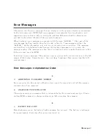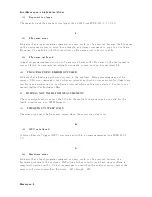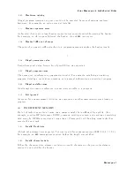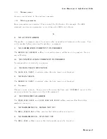
Error
Messages
in
Alphabetical
Order
0138
Sux
not
allow
ed
A
sux
w
as
encoun
tered
after
a
n
umeric
elemen
t
that
do es
not
allo w
suxes.
0134
Sux
to
o
long
The
sux
con
tained
more
than
12
c
haracters
(see
IEEE
488.2,
7.7.3.4).
0102
Syn
tax
error
An
unrecognized
command
or
data
t
yp e
w
as
encoun
tered.
F
or
example,
a
string
w
as
receiv
ed
when
the
analyzer
w
as
not
exp ecting
to
receiv
e
a
string.
0310
System
error
Some
error,
termed
\system
error"
b
y
the
analyzer,
has
o ccurred.
T
0124
T
o o
man
y
digits
The
man
tissa
of
a
decimal
n
umeric
data
elemen
t
con
tains
more
than
255
digits
excluding
leading
zeros
(see
IEEE
488.2,
7.7.2.4.1).
77
TOO
MANY
SEGMENTS
OR
POINTS
F
requency
list
mo
de
is
limited
to
31
segmen
ts
or
801
p oints.
64
TOO
MANY
SEGMENTS
The
maxim
um
n
um
b er
of
segmen
ts
for
the
limit
line
table
is
18.
0223
T
o o
m
uc
h
data
A
legal
program
data
elemen
t
of
blo
c
k,
expression,
or
string
t
yp e
w
as
receiv
ed
that
con
tained
more
data
than
the
analyzer
could
handle
due
to
memory
or
related
device-sp ecic
requiremen
ts.
54
TOO
MUCH
D
A
T
A
Either
there
is
to
o
m
uc
h
binary
data
to
send
to
the
analyzer
when
the
data
transfer
format
is
F
ORM
2,
F
ORM
3
or
F
ORM
5,
or
the
amoun
t
of
data
is
greater
than
the
n
um
b er
of
p oints.
78
TOO
SMALL
POINTS
OR
TOO
LAR
GE
STOP
STOP+SP
AN/(NOP0 1)
is
out
of
sw
eep
range.
Increase
NOP
or
c
hange
STOP
v
alue
to
low
er
frequency
to
a
v
oid
this
error.
0210
T
rigger
error
A
trigger
related
error
o ccurred.
This
error
message
is
used
when
the
analyzer
cannot
detect
the
more
sp ecic
errors
describ ed
for
errors
0211
through
0219.
Messages-14
Summary of Contents for 4395A
Page 10: ......
Page 26: ......
Page 34: ......
Page 77: ...Figure 2 17 B R Magnitude Ratio Phase Dynamic Accuracy Test Setup 2 Performance Tests 2 43 ...
Page 167: ...Figure 5 1 Adjustment Hardware Setup Adjustments 5 5 ...
Page 186: ...Figure 5 13 Receiver Gain Adjustment Location 5 24 Adjustments ...
Page 190: ...Figure 5 16 Receiver Flatness Adjustment Setup 1 MHz 5 28 Adjustments ...
Page 194: ...Figure 5 20 DC Bias Adjustment Setup 2 5 32 Adjustments ...
Page 196: ...Figure 6 1 Troubleshooting Organization 6 2 Troubleshooting ...
Page 206: ...Figure 7 1 Power Supply Lines Simplified Block Diagram 7 2 Power Supply Troubleshooting ...
Page 212: ...Figure 7 5 A1 CPU Connector Locations 7 8 Power Supply Troubleshooting ...
Page 220: ...Figure 8 1 Digital Control Group Simplified Block Diagram 8 2 Digital Control Troubleshooting ...
Page 240: ...Figure 10 1 Top View Major Assemblies 10 4 Replaceable Parts ...
Page 292: ...Table A 2 Manual Changes by Firmware Version Version Make Manual Changes A 2 Manual Changes ...
Page 308: ......
Page 311: ...Figure B 1 Power Cable Supplied Power Requirement B 3 ...
Page 312: ......
Page 342: ......


