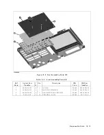


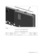


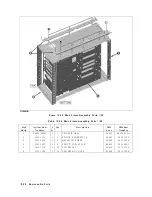


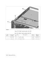


Figure
10-23.
Rear
Assembly
P
arts
8/8
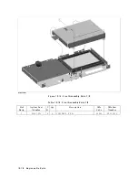
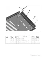
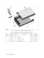
T
able
10-25.
Rear
Assembly
P
arts
8/8
Ref.
Desig.
Agilent
P
art
Numb er
C
D
Qt
y
.
Description
Mfr
Co de
Mfr
P
art
Numb er
1
E5100-61640
6
3
WIRE
ASSY
GND
28480
E5100-61640
2
04396-61706
2
1
CABLE
ASSY
28480
04396-61706
3
1400-0611
0
1
CLAMP-CABLE
28480
1400-0611
4
1400-1334
6
1
CLAMP
CABLE
28480
1400-1334
Replaceable
P
arts
10-27
Summary of Contents for 4395A
Page 10: ......
Page 26: ......
Page 34: ......
Page 77: ...Figure 2 17 B R Magnitude Ratio Phase Dynamic Accuracy Test Setup 2 Performance Tests 2 43 ...
Page 167: ...Figure 5 1 Adjustment Hardware Setup Adjustments 5 5 ...
Page 186: ...Figure 5 13 Receiver Gain Adjustment Location 5 24 Adjustments ...
Page 190: ...Figure 5 16 Receiver Flatness Adjustment Setup 1 MHz 5 28 Adjustments ...
Page 194: ...Figure 5 20 DC Bias Adjustment Setup 2 5 32 Adjustments ...
Page 196: ...Figure 6 1 Troubleshooting Organization 6 2 Troubleshooting ...
Page 206: ...Figure 7 1 Power Supply Lines Simplified Block Diagram 7 2 Power Supply Troubleshooting ...
Page 212: ...Figure 7 5 A1 CPU Connector Locations 7 8 Power Supply Troubleshooting ...
Page 220: ...Figure 8 1 Digital Control Group Simplified Block Diagram 8 2 Digital Control Troubleshooting ...
Page 240: ...Figure 10 1 Top View Major Assemblies 10 4 Replaceable Parts ...
Page 292: ...Table A 2 Manual Changes by Firmware Version Version Make Manual Changes A 2 Manual Changes ...
Page 308: ......
Page 311: ...Figure B 1 Power Cable Supplied Power Requirement B 3 ...
Page 312: ......
Page 342: ......


