


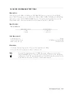


18.
SECOND
HARMONIC
DISTORTION
TEST
(SA)
Description
This
test
measures
the
second
harmonics
lev
el
generated
within
the
4395A
at
a
frequency
of
50.1
MHz
in
the
4395A
sp ectrum
analyzer
mo
de.
This
test
applies
a
50.1
MHz
CW
frequency
signal
to
the
4395A
R
input
through
a
50
MHz
low
pass
lter
(LPF).
The
LPF
remov
es
the
second
harmonics
included
in
the
applied
signal.
This
ensures
that
the
harmonics
read
b
y
the
4395A
are
in
ternally
generated
and
not
coming
from
the
external
signal
source.
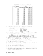
Specification
Second
harmonic
distortion
@input
signal
freq.
100
kHz
1
:
:
:
:
:
:
:
:
:
:
:
:
:
:
:
:
:
:
:
:
:
:
:
:
:
:
:
:
:
:
:
:
:
:
:
:
:
:
:
:
:
:
:
:
:
:
<070
dBc
1:
single
tone
input
with
full
scale
input 010
dB
T
est
Equipment
Signal
Generator
:
:
:
:
:
:
:
:
:
:
:
:
:
:
:
:
:
:
:
:
:
:
:
:
:
:
:
:
:
:
:
:
:
:
:
:
:
:
:
:
:
:
:
:
:
:
:
:
:
:
:
:
:
:
:
:
:
:
:
:
:
:
:
:
:
:
:
8642B
P
o
w
er
Meter
:
:
:
:
:
:
:
:
:
:
:
:
:
:
:
:
:
:
:
:
:
:
:
:
:
:
:
:
:
:
:
:
:
:
:
:
:
:
:
:
:
:
:
:
:
:
:
436A
Opt.
022,
437B,
or
438A
P
o
w
er
Sensor
:
:
:
:
:
:
:
:
:
:
:
:
:
:
:
:
:
:
:
:
:
:
:
:
:
:
:
:
:
:
:
:
:
:
:
:
:
:
:
:
:
:
:
:
:
:
:
:
:
:
:
:
:
:
:
:
:
:
:
:
:
:
:
:
:
:
:
:
:
:
:
8482A
50
MHz
Lo
w
P
ass
Filter
:
:
:
:
:
:
:
:
:
:
:
:
:
:
:
:
:
:
:
:
:
:
:
:
:
:
:
:
:
:
:
:
:
:
:
:
:
:
:
:
:
:
:
:
:
:
:
:
:
:
:
:
:
PN
0955-0306
Tw
o-W
a
y
P
o
w
er
Splitter
:
:
:
:
:
:
:
:
:
:
:
:
:
:
:
:
:
:
:
:
:
:
:
:
:
:
:
:
:
:
:
:
:
:
:
:
:
:
:
:
:
:
:
:
:
:
:
:
:
:
:
:
:
:
:
:
:
:
:
11667A
BNC
cable,
61
cm
(tw
o
required)
:
:
:
:
:
:
:
:
:
:
:
:
:
:
:
:
:
:
:
:
:
:
:
:
:
:
:
:
:
:
:
:
:
:
:
:
:
:
:
:
:
:
:
:
PN
8120-1839
BNC
cable,
122
cm
:
:
:
:
:
:
:
:
:
:
:
:
:
:
:
:
:
:
:
:
:
:
:
:
:
:
:
:
:
:
:
:
:
:
:
:
:
:
:
:
:
:
:
:
:
:
:
:
:
:
:
:
:
:
:
:
:
PN
8120-1839
BNC(f
)-BNC(f
)
adapter
:
:
:
:
:
:
:
:
:
:
:
:
:
:
:
:
:
:
:
:
:
:
:
:
:
:
:
:
:
:
:
:
:
:
:
:
:
:
:
:
:
:
:
:
:
:
:
:
:
:
:
:
PN
1250-0080
N(m)-N(m)
adapter
:
:
:
:
:
:
:
:
:
:
:
:
:
:
:
:
:
:
:
:
:
:
:
:
:
:
:
:
:
:
:
:
:
:
:
:
:
:
:
:
:
:
:
:
:
:
:
:
:
:
:
:
:
:
:
:
:
PN
1250-1475
N(m)-BNC(f
)
adapter
(tw
o
required)
:
:
:
:
:
:
:
:
:
:
:
:
:
:
:
:
:
:
:
:
:
:
:
:
:
:
:
:
:
:
:
:
:
:
:
:
:
:
:
:
PN
1250-0780
Procedure
1.
Initialize
the
signal
generator.
Then
set
the
signal
generator
con
trols
as
follows:
Con
trols
Settings
F
requency
50.1
MHz
Amplitude
014
dBm
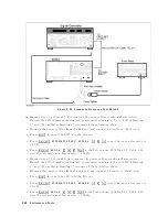
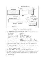
2.
Connect
the
test
equipmen
t
as
sho
wn
in
Figure
2-27.
Note
Connect
the
signal
generator's
10
MHz
frequency
reference
output
to
the
4395A
EXT
REF
Input
on
the
rear
panel
as
sho
wn
in
Figure
2-27 .
With
this
conguration,
b oth
the
signal
generator
and
the
4395A
are
phase
lo
c
k
ed
to
the
same
reference
frequency
to
obtain
a
stable
measuremen
t.
P
erformance
T
ests
2-71
Summary of Contents for 4395A
Page 10: ......
Page 26: ......
Page 34: ......
Page 77: ...Figure 2 17 B R Magnitude Ratio Phase Dynamic Accuracy Test Setup 2 Performance Tests 2 43 ...
Page 167: ...Figure 5 1 Adjustment Hardware Setup Adjustments 5 5 ...
Page 186: ...Figure 5 13 Receiver Gain Adjustment Location 5 24 Adjustments ...
Page 190: ...Figure 5 16 Receiver Flatness Adjustment Setup 1 MHz 5 28 Adjustments ...
Page 194: ...Figure 5 20 DC Bias Adjustment Setup 2 5 32 Adjustments ...
Page 196: ...Figure 6 1 Troubleshooting Organization 6 2 Troubleshooting ...
Page 206: ...Figure 7 1 Power Supply Lines Simplified Block Diagram 7 2 Power Supply Troubleshooting ...
Page 212: ...Figure 7 5 A1 CPU Connector Locations 7 8 Power Supply Troubleshooting ...
Page 220: ...Figure 8 1 Digital Control Group Simplified Block Diagram 8 2 Digital Control Troubleshooting ...
Page 240: ...Figure 10 1 Top View Major Assemblies 10 4 Replaceable Parts ...
Page 292: ...Table A 2 Manual Changes by Firmware Version Version Make Manual Changes A 2 Manual Changes ...
Page 308: ......
Page 311: ...Figure B 1 Power Cable Supplied Power Requirement B 3 ...
Page 312: ......
Page 342: ......


