


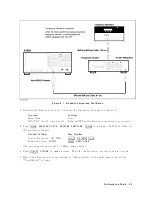


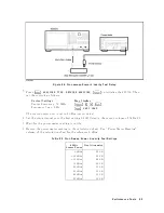


Figure
2-2.
Source
Lev
el
Accuracy
T
est
Setup
3.
Press
4
Meas
5,
NNNNNNNNNNNNNNNNNNNNNNNNNNNNNNNNNNNNNNNNN
ANALYZER
TYPE
,
NNNNNNNNNNNNNNNNNNNNNNNNNNNNNNNNNNNNNNNNNNNNNNNNNN
NETWORK
ANALYZER
,
4
Preset
5
to
initialize
the
4395A.
Then
set
the
con
trols
as
follo
ws:
Con
trol
Settings
Key
Strok
es
Cen
ter
F
requency:
50
MHz
4
Center
5,
4
5
5,
4
0
5,
4
M/
5
F
requency
Span:
0
Hz
4
Span
5,
NNNNNNNNNNNNNNNNNNNNNNNNNNNNNNNNNNN
ZERO
SPAN
The
source
p o
w
er
no
w
is
set
to
0
dBm
(preset
v
alue).
4.
Source
Lev
el
Accuracy
T
est
a.
W
ait
for
the
p o
w
er
meter
reading
to
settle.
b.
Record
the
p o
w
er
meter
reading
in
the
p erformance
test
record
(\T
est
Result"
column
for
the
lev
el
accuracy
test).
5.
Source
Lev
el
Flatness
T
est
(High
F
requencies)
a.
Record
the
test
result
of
the
lev
el
accuracy
test
in
the
calculation
sheet
(\Po
w
er
Meter
Reading
[ref
]"
column
for
the
lev
el
atness
test).
b.
Press
4
Center
5,
4
1
5,
4
M/
5
to
c
hange
the
4395A
cen
ter
frequency
to
the
rst
atness
test
frequency
1
MHz
listed
in
T
able
2-1.
T
able
2-1
lists
atness
test
p oints
for
high
frequencies.
P
erformance
T
ests
2-5
Summary of Contents for 4395A
Page 10: ......
Page 26: ......
Page 34: ......
Page 77: ...Figure 2 17 B R Magnitude Ratio Phase Dynamic Accuracy Test Setup 2 Performance Tests 2 43 ...
Page 167: ...Figure 5 1 Adjustment Hardware Setup Adjustments 5 5 ...
Page 186: ...Figure 5 13 Receiver Gain Adjustment Location 5 24 Adjustments ...
Page 190: ...Figure 5 16 Receiver Flatness Adjustment Setup 1 MHz 5 28 Adjustments ...
Page 194: ...Figure 5 20 DC Bias Adjustment Setup 2 5 32 Adjustments ...
Page 196: ...Figure 6 1 Troubleshooting Organization 6 2 Troubleshooting ...
Page 206: ...Figure 7 1 Power Supply Lines Simplified Block Diagram 7 2 Power Supply Troubleshooting ...
Page 212: ...Figure 7 5 A1 CPU Connector Locations 7 8 Power Supply Troubleshooting ...
Page 220: ...Figure 8 1 Digital Control Group Simplified Block Diagram 8 2 Digital Control Troubleshooting ...
Page 240: ...Figure 10 1 Top View Major Assemblies 10 4 Replaceable Parts ...
Page 292: ...Table A 2 Manual Changes by Firmware Version Version Make Manual Changes A 2 Manual Changes ...
Page 308: ......
Page 311: ...Figure B 1 Power Cable Supplied Power Requirement B 3 ...
Page 312: ......
Page 342: ......


