


P
erformance
T
ests
F
ailure
Troubleshooting
P
erform
the
follo wing
pro cedure
sequen
tially
when
an
y
of
p erformance
tests
fail.
P
erform
Adjustments
and
Correction
Constants
T
able
6-3
gives
the
recommended
adjustmen
ts
and
correction
constan
ts
when
a
p erformance
test
fails.
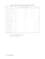
If
a
p erformance
test
fails,
y
ou
should
p erform
the
corresp onding
adjustmen
ts
or
correction
constan
ts
function
as
sho
wn
in
T
able
6-3 .
If
the
tests
still
fail,
refer
to
T
able
6-4
and
replace
the
assem
bly
.
Note
that
this
table
lists
some
t
ypical
cases.
In
a
few
cases,
other
assem
bly
may
actually
b e
faulty
.
T
able
6-3.
Troubleshooting
Information
for
P
erformance
T
est
F
ailure
1
T
est
No.
F
ailed
T
est
Adjustment
T
est
Num
b er
1
2
3
4
5
6
7
8
9
10
11
12
13
14
15
1
F
requency
Accuracy
T
est
p
p
p
p
p
p
p
2
Source
Level
Accuracy/Flatness
T
est
p
p
p
p
p
p
p
3
Non-sw
eep
Linearity
T
est
p
p
p
p
p
p
p
4
P
o
w
er
Sweep
Linearity
T
est
p
p
p
p
p
p
p
5
Harmonics/Non-harmonic
T
est
p
p
p
p
p
p
p
6
DC
Bias
T
est
p
7
Receiv er
Noise
Level
T
est
p
p
p
p
p
p
p
p
p
8
Input
Crosstalk
T
est
p
p
p
p
p
p
9
Input
Imp edance
T
est
p
p
p
p
p
p
10
Absolute
Amplitude
Accuracy
T
est
p
p
p
p
p
p
p
p
p
p
p
11
Magnitude
Ratio/Phase
Dynamic
Accuracy
T
est
p
p
p
p
p
p
p
p
p
12
Magnitude
Ratio/Phase
F
requency
Resp
onse
T
est
p
p
p
p
p
p
p
p
p
13
Display
ed
Av
erage
Noise
Level
T
est
p
p
p
p
p
p
p
p
p
p
p
14
Amplitude
Fidelity
T
est
p
p
p
p
p
p
p
p
p
p
15
Input
A
ttenuator
Switching
Uncertaint
y
T
est
p
p
p
p
16
Noise
Sidebands
T
est
p
p
p
p
p
p
17
Amplitude
Accuracy/F
requency
Resp
onse
T
est
p
p
p
p
p
p
p
p
p
p
18
Second
Harmonic
Distortion
T
est
p
p
p
p
p
19
Third
Order
In
termo dulation
Distortion
T
est
p
p
p
p
p
p
p
p
p
p
p
20
Other
Spurious
T
est
p
p
p
p
p
p
p
p
p
p
p
21
Residual
Resp
onse
T
est
p
p
p
p
p
p
p
p
p
p
p
Troubleshooting
6-9
Summary of Contents for 4395A
Page 10: ......
Page 26: ......
Page 34: ......
Page 77: ...Figure 2 17 B R Magnitude Ratio Phase Dynamic Accuracy Test Setup 2 Performance Tests 2 43 ...
Page 167: ...Figure 5 1 Adjustment Hardware Setup Adjustments 5 5 ...
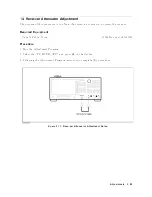
Page 186: ...Figure 5 13 Receiver Gain Adjustment Location 5 24 Adjustments ...
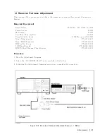
Page 190: ...Figure 5 16 Receiver Flatness Adjustment Setup 1 MHz 5 28 Adjustments ...
Page 194: ...Figure 5 20 DC Bias Adjustment Setup 2 5 32 Adjustments ...
Page 196: ...Figure 6 1 Troubleshooting Organization 6 2 Troubleshooting ...
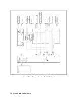
Page 206: ...Figure 7 1 Power Supply Lines Simplified Block Diagram 7 2 Power Supply Troubleshooting ...
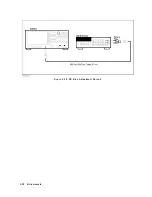
Page 212: ...Figure 7 5 A1 CPU Connector Locations 7 8 Power Supply Troubleshooting ...
Page 220: ...Figure 8 1 Digital Control Group Simplified Block Diagram 8 2 Digital Control Troubleshooting ...
Page 240: ...Figure 10 1 Top View Major Assemblies 10 4 Replaceable Parts ...
Page 292: ...Table A 2 Manual Changes by Firmware Version Version Make Manual Changes A 2 Manual Changes ...
Page 308: ......
Page 311: ...Figure B 1 Power Cable Supplied Power Requirement B 3 ...
Page 312: ......
Page 342: ......


