


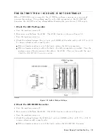


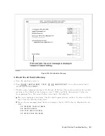


Figure
8-4.
Bootloader
Menu
Display
4.
Insert
the
rm
w
are
disk
ette
in
to
the
opp
y
disk
driv
e
on
the
fron
t
panel.
5.
Press
NNNNNNNNNNNNNNNNNNNNNNNNNNNNNNNNNNNNNNNNN
SYSTEM
UPDATE
and
NNNNNNNNNNNNNNNNNNNNNNNNNN
CONTINUE
.
The
analyzer
displays
\Loading
F
rom
Disk"
and
starts
the
rm
w
are
installation.
6.
W
ait
un
til
the
analyzer
displays
\Up date
Complete."
7.
Press
NNNNNNNNNNNNNNNNNNNN
REBOOT
or
turn
the
analyzer
p o
w
er
o
and
on.
The
analyzer
starts
the
op eration
using
the
installed
rm
w
are.
8.
V
erify
that
no
error
message
is
display
ed
and
that
the
revision
display
ed
is
that
of
the
revision
lab
el.
In
case
of
unexpected
results,
insp ect
the
rm
w
are
disk
ette
for
an
y
damage.
Clean
the
built-in
FDD
and
retry
the
pro cedure.
Digital
Control
Troubleshooting
8-5
Summary of Contents for 4395A
Page 10: ......
Page 26: ......
Page 34: ......
Page 77: ...Figure 2 17 B R Magnitude Ratio Phase Dynamic Accuracy Test Setup 2 Performance Tests 2 43 ...
Page 167: ...Figure 5 1 Adjustment Hardware Setup Adjustments 5 5 ...
Page 186: ...Figure 5 13 Receiver Gain Adjustment Location 5 24 Adjustments ...
Page 190: ...Figure 5 16 Receiver Flatness Adjustment Setup 1 MHz 5 28 Adjustments ...
Page 194: ...Figure 5 20 DC Bias Adjustment Setup 2 5 32 Adjustments ...
Page 196: ...Figure 6 1 Troubleshooting Organization 6 2 Troubleshooting ...
Page 206: ...Figure 7 1 Power Supply Lines Simplified Block Diagram 7 2 Power Supply Troubleshooting ...
Page 212: ...Figure 7 5 A1 CPU Connector Locations 7 8 Power Supply Troubleshooting ...
Page 220: ...Figure 8 1 Digital Control Group Simplified Block Diagram 8 2 Digital Control Troubleshooting ...
Page 240: ...Figure 10 1 Top View Major Assemblies 10 4 Replaceable Parts ...
Page 292: ...Table A 2 Manual Changes by Firmware Version Version Make Manual Changes A 2 Manual Changes ...
Page 308: ......
Page 311: ...Figure B 1 Power Cable Supplied Power Requirement B 3 ...
Page 312: ......
Page 342: ......


