


T
able
11-1.
P
ost
Repair
Procedures
(continued)
Replaced
Assembly
or
P
art
Adjustments
Correction
Constants
V
erication
A9
Input
Multiplexer
Input
DC
Oset
Adjustmen
t
INSPECT
THE
PO
WER
ON
SEQUENCE
1
Input
Lo
cal
Null
Adjustmen t
Receiver
Noise
Level
Receiv er
Gain
Adjustmen
t
Input
Crosstalk
IF
8
dB/16
dB
Gain
Adjustmen t
Input
Imp edance
Receiv er
Flatness
Adjustmen t
Absolute
Amplitude
Accuracy
Receiv er
A
ttnuator
Adjustmen
t
Magnitude
Ratio/Phase
Dynamic
Accuracy
IF
BPF
Flatness
Adjustmen t
Magnitude
Ratio/Phase
F
requency
Resp
onse
Displa
yed
Av
erage
Noise
Level
Amplitude
Fidelity
Input
A
tten uator
Switching
Uncertaint
y
Amplitude
Accuracy/F
requency
Resp
onse
Second
Harmonic
Distortion
Third
Order
Intermo dulation
Distortion
Other
Spurious
Residual
Resp
onse
A20
Mother
Board
None
INSPECT
THE
PO
WER
ON
SEQUENCE
1
A30
F
ront
Keyb
oard
None
INSPECT
THE
PO
WER
ON
SEQUENCE
1
External
T
est
50:
FR
ONT
P
ANEL
DIA
G
2
A32
IBASIC
I/F
None
INSPECT
THE
PO
WER
ON
SEQUENCE
1
Che
ck
the
A32
I-BASIC
Interfac
e
and
the
mini
DIN
Keyb
o
ar
d
2
A33
EXT
I/O
None
INSPECT
THE
PO
WER
ON
SEQUENCE
1
External
T
est
52:
24
BIT
I/O
POR
T
2
A40
Pre-Regulator
DC
Bias
Adjustmen
t
INSPECT
THE
PO
WER
ON
SEQUENCE
1
A50
DC-DC
Con
verter
None
INSPECT
THE
PO
WER
ON
SEQUENCE
1
A51
GSP
None
INSPECT
THE
PO
WER
ON
SEQUENCE
1
A52
LCD
None
INSPECT
THE
PO
WER
ON
SEQUENCE
1
A53
FDD
None
INSPECT
THE
PO
WER
ON
SEQUENCE
1
External
T
est
51:
DSK
DR
F
A
UL
TY
ISOLN
2
1
See
the
T
r
oublesho
oting
c
hapter.
2
See
the
Digital
Contr
ol
T
r
oublesho
oting
c
hapter.
11-4
P
ost
Repair
Procedures
Summary of Contents for 4395A
Page 10: ......
Page 26: ......
Page 34: ......
Page 77: ...Figure 2 17 B R Magnitude Ratio Phase Dynamic Accuracy Test Setup 2 Performance Tests 2 43 ...
Page 167: ...Figure 5 1 Adjustment Hardware Setup Adjustments 5 5 ...
Page 186: ...Figure 5 13 Receiver Gain Adjustment Location 5 24 Adjustments ...
Page 190: ...Figure 5 16 Receiver Flatness Adjustment Setup 1 MHz 5 28 Adjustments ...
Page 194: ...Figure 5 20 DC Bias Adjustment Setup 2 5 32 Adjustments ...
Page 196: ...Figure 6 1 Troubleshooting Organization 6 2 Troubleshooting ...
Page 206: ...Figure 7 1 Power Supply Lines Simplified Block Diagram 7 2 Power Supply Troubleshooting ...
Page 212: ...Figure 7 5 A1 CPU Connector Locations 7 8 Power Supply Troubleshooting ...
Page 220: ...Figure 8 1 Digital Control Group Simplified Block Diagram 8 2 Digital Control Troubleshooting ...
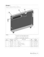
Page 240: ...Figure 10 1 Top View Major Assemblies 10 4 Replaceable Parts ...
Page 292: ...Table A 2 Manual Changes by Firmware Version Version Make Manual Changes A 2 Manual Changes ...
Page 308: ......
Page 311: ...Figure B 1 Power Cable Supplied Power Requirement B 3 ...
Page 312: ......
Page 342: ......


