


4.
Remo
v
e
Assemblies
a.
T
urn
the
analyzer
p o
w
er
o.
Remo
v
e
the
assem
blies,
A2,
A3,
A5,
A7,
A8
and
A51.
b.
T
urn
the
analyzer
p o
w
er
on.
Lo ok
at
the
A1
+5
VD
LED.
If
the
LED
is
still
o,
insp ect
the
A20
motherb oard.
If
the
LED
go
es
on,
the
A20
motherb oard
are
v
eried.
Con
tin
ue
with
the
next
step.
c.
Reinstall
one
of
the
remov
ed
assem
blies
at
a
time.
T
urn
the
analyzer
p o
w
er
on
after
eac
h
is
installed.
The
assem
bly
that
turns
the
A1
+5
VD
LED
on
is
the
most
probable
faulty
assem
bly
.
Replace
the
assem
bly
.
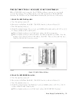
5.
Remo
v
e
Assemblies
a.
T
urn
the
analyzer
p o
w
er
o.
Remo
v
e
the
assem
blies,
A2,
A3,
A5,
A7,
A8,
A51
and
A9J2.
b.
T
urn
the
analyzer
p o
w
er
on.
Lo ok
at
the
A1
+5
VD
LED.
If
the
LED
is
still
o,
insp ect
the
A20
motherb oard.
If
the
LED
go
es
on,
the
A20
motherb oard
are
v
eried.
Con
tin
ue
with
the
next
step.
c.
Reinstall
one
of
the
remov
ed
assem
blies
at
a
time.
T
urn
the
analyzer
p o
w
er
on
after
eac
h
is
installed.
The
assem
bly
that
turns
the
A1
+5
VD
LED
on
is
the
most
probable
faulty
assem
bly
.
Replace
the
assem
bly
.
P
o
w
er
Supply
Troubleshooting
7-11
Summary of Contents for 4395A
Page 10: ......
Page 26: ......
Page 34: ......
Page 77: ...Figure 2 17 B R Magnitude Ratio Phase Dynamic Accuracy Test Setup 2 Performance Tests 2 43 ...
Page 167: ...Figure 5 1 Adjustment Hardware Setup Adjustments 5 5 ...
Page 186: ...Figure 5 13 Receiver Gain Adjustment Location 5 24 Adjustments ...
Page 190: ...Figure 5 16 Receiver Flatness Adjustment Setup 1 MHz 5 28 Adjustments ...
Page 194: ...Figure 5 20 DC Bias Adjustment Setup 2 5 32 Adjustments ...
Page 196: ...Figure 6 1 Troubleshooting Organization 6 2 Troubleshooting ...
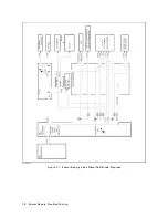
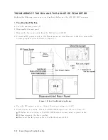
Page 206: ...Figure 7 1 Power Supply Lines Simplified Block Diagram 7 2 Power Supply Troubleshooting ...
Page 212: ...Figure 7 5 A1 CPU Connector Locations 7 8 Power Supply Troubleshooting ...
Page 220: ...Figure 8 1 Digital Control Group Simplified Block Diagram 8 2 Digital Control Troubleshooting ...
Page 240: ...Figure 10 1 Top View Major Assemblies 10 4 Replaceable Parts ...
Page 292: ...Table A 2 Manual Changes by Firmware Version Version Make Manual Changes A 2 Manual Changes ...
Page 308: ......
Page 311: ...Figure B 1 Power Cable Supplied Power Requirement B 3 ...
Page 312: ......
Page 342: ......


