


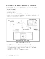


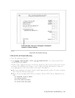


2.
Troubleshoot
the
A50
DC-DC
Conv
erter
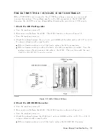
Figure
7-9.
A50
DC-DC
Conv
erter
Troubleshooting
Setup
a.
T
urn
the
analyzer
p o
w
er
o.
b.
Disconnect
cables
from
the
A50J3.
The
connector
lo
cations
are
sho
wn
in
Figure
7-9
c.
Connect
the
pulse
generator
to
the
A50J2
as
sho
wn
in
Figure
7-9.
The
pulse
generator
is
used
to
feed
the
substitute
of
the
F
AN
LOCK
signal
to
the
A50
DC-DC
con
v
erter.
This
purp oses
not
to
sh
ut
do
wn
the
A50
DC-DC
con
v
erter.
d.
T
urn
the
pulse
generator
p o
w
er
on.
Set
the
con
trols
as
follo ws:
W
a
v
e
F
orm
Square
F
requency
Appro
ximately
30
Hz
Amplitude
+7.8
V
e.
Connect
a
resister
(app o
ximately
680ohms,
125mW)
b et
w
een
the
A50J2
pin
5
(+7.8
V)
and
pin
4(GND)
as
sho
wn
in
Figure
7-9 .
f.
T
urn
the
analyzer
p o
w
er
on.
g.
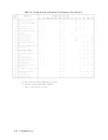
Measure
all
p o
w
er
supply
v
oltages
on
A50J2
and
A50J3
using
a
v
oltmeter
with
a
small
prob e.
See
the
T
able
7-1
for
p o
w
er
lines,
connector
pins,
and
limits.
P
o
w
er
Supply
Troubleshooting
7-13
Summary of Contents for 4395A
Page 10: ......
Page 26: ......
Page 34: ......
Page 77: ...Figure 2 17 B R Magnitude Ratio Phase Dynamic Accuracy Test Setup 2 Performance Tests 2 43 ...
Page 167: ...Figure 5 1 Adjustment Hardware Setup Adjustments 5 5 ...
Page 186: ...Figure 5 13 Receiver Gain Adjustment Location 5 24 Adjustments ...
Page 190: ...Figure 5 16 Receiver Flatness Adjustment Setup 1 MHz 5 28 Adjustments ...
Page 194: ...Figure 5 20 DC Bias Adjustment Setup 2 5 32 Adjustments ...
Page 196: ...Figure 6 1 Troubleshooting Organization 6 2 Troubleshooting ...
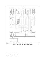
Page 206: ...Figure 7 1 Power Supply Lines Simplified Block Diagram 7 2 Power Supply Troubleshooting ...
Page 212: ...Figure 7 5 A1 CPU Connector Locations 7 8 Power Supply Troubleshooting ...
Page 220: ...Figure 8 1 Digital Control Group Simplified Block Diagram 8 2 Digital Control Troubleshooting ...
Page 240: ...Figure 10 1 Top View Major Assemblies 10 4 Replaceable Parts ...
Page 292: ...Table A 2 Manual Changes by Firmware Version Version Make Manual Changes A 2 Manual Changes ...
Page 308: ......
Page 311: ...Figure B 1 Power Cable Supplied Power Requirement B 3 ...
Page 312: ......
Page 342: ......


