


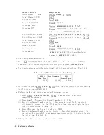


i.
On
the
4395A,
set
the
con
trols
as
follo ws:
Con
trol
Settings
Key
Strok
es
Source
P
o
w
er:
8
dBm
4
Source
5,
NNNNNNNNNNNNNNNNN
POWER
,
4
8
5,
4
x1
5
Active
Channel:
CH
1
4
Ch
1
5
Av
eraging
F
actor:
4
4
Bw/Avg
5,
NNNNNNNNNNNNNNNNNNNNNNNNNNNNNNNNNNNNNNNNNNNNNNNNNN
AVERAGING
FACTOR
,
4
4
5,
4
x1
5
Active
Channel:
CH
2
4
Ch
2
5
Av
eraging
F
actor:
4
4
Bw/Avg
5,
NNNNNNNNNNNNNNNNNNNNNNNNNNNNNNNNNNNNNNNNNNNNNNNNNN
AVERAGING
FACTOR
,
4
4
5,
4
x1
5
Input
A
tten
uator
R:
10dB
4
Scale
Ref
5,
NNNNNNNNNNNNNNNNNNNNNNNNNNNNNNNNNNNNNNNNNNNNNNN
ATTENUATOR
MENU
,
NNNNNNNNNNNNNNNNNNNNNNN
ATTEN
R
,
4
1
5,
4
0
5,
4
x1
5
Input
A
tten
uator
B:
0dB
4
Scale
Ref
5,
NNNNNNNNNNNNNNNNNNNNNNNNNNNNNNNNNNNNNNNNNNNNNNN
ATTENUATOR
MENU
,
NNNNNNNNNNNNNNNNNNNNNNN
ATTEN
B
,
4
0
5,
4
x1
5
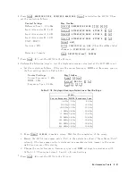
j.
Set
the
step
attenuator
to
10
dB.
k.
Press
4
Cal
5,
NNNNNNNNNNNNNNNNNNNNNNNNNNNNNNNNNNNNNNNNNNNN
CALIBRATE
MENU
,
NNNNNNNNNNNNNNNNNNNNNNNNNN
RESPONSE
,
NNNNNNNNNNNNNN
THRU
to
p erform
the
resp onse
(THR
U)
calibration.
W
ait
for
the
completion
of
the
sw
eep.
Then
press
NNNNNNNNNNNNNNNNNNNNNNNNNNNNNNNNNNNNNNNNN
DONE:RESPONSE
.
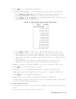
l.
Set
the
step
attenuator
to
the
rst
setting
20dB
in
the
second
colum
of
T
able
2-17 .
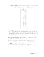
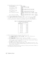
T
able
2-17.
B/R
Dynamic
Accuracy
T
est
Settings
2
4395A
Input
Lev
el
Step
A
tten
uator
020
dB
20
dB
030
dB
30
dB
040
dB
40
dB
050
dB
50
dB
060
dB
60
dB
070
dB
70
dB
080
dB
80
dB
090
dB
90
dB
0100
dB
100
dB
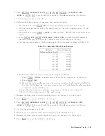
m.
P
erform
the
following
steps
to
measure
the
dynamic
accuracy
.
i.
Press
4
T
rigger
5,
NNNNNNNNNNNNNNNNNNNNNNNNNNNNNNNNNNNNNNNNNNNNNNNNNN
NUMBER
OF
GROUPS
,
4
5
5,
4
x1
5
to
make
a
sw
eep.
W
ait
for
the
completion
of
the
sw
eep.
ii.
Press
4
Ma
rk
er
5,
4
*
5
to
mov
e
the
c
hannel
1
marker
to
50.1
MHz.
iii.
Record
the
c
hannel
1
marker
reading
in
the
calculation
sheet
for
the
magnitude
ratio
dynamic
accuracy
.
Use
the
4395A
reading
column
corresp onding
to
the
input
lev
el
in
the
rst
column
of
T
able
2-17 .
iv.
Press
4
+
5
to
mov
e
the
c
hannel
2
marker
to
3
MHz.
v.
Record
the
c
hannel
2
marker
reading
directly
in
the
p erformance
test
record.
Use
the
test
result
column
of
the
phase
measuremen
t
corresp onding
to
the
input
lev
el
in
the
rst
column
of
T
able
2-17.
n.
Change
the
step
attenuator
setting
in
accordance
with
the
second
column
of
T
able
2-17,
and
p erform
step
4-m
for
eac
h
setting.
2-44
P
erformance
T
ests
Summary of Contents for 4395A
Page 10: ......
Page 26: ......
Page 34: ......
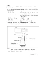
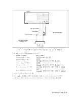
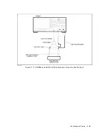
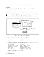
Page 77: ...Figure 2 17 B R Magnitude Ratio Phase Dynamic Accuracy Test Setup 2 Performance Tests 2 43 ...
Page 167: ...Figure 5 1 Adjustment Hardware Setup Adjustments 5 5 ...
Page 186: ...Figure 5 13 Receiver Gain Adjustment Location 5 24 Adjustments ...
Page 190: ...Figure 5 16 Receiver Flatness Adjustment Setup 1 MHz 5 28 Adjustments ...
Page 194: ...Figure 5 20 DC Bias Adjustment Setup 2 5 32 Adjustments ...
Page 196: ...Figure 6 1 Troubleshooting Organization 6 2 Troubleshooting ...
Page 206: ...Figure 7 1 Power Supply Lines Simplified Block Diagram 7 2 Power Supply Troubleshooting ...
Page 212: ...Figure 7 5 A1 CPU Connector Locations 7 8 Power Supply Troubleshooting ...
Page 220: ...Figure 8 1 Digital Control Group Simplified Block Diagram 8 2 Digital Control Troubleshooting ...
Page 240: ...Figure 10 1 Top View Major Assemblies 10 4 Replaceable Parts ...
Page 292: ...Table A 2 Manual Changes by Firmware Version Version Make Manual Changes A 2 Manual Changes ...
Page 308: ......
Page 311: ...Figure B 1 Power Cable Supplied Power Requirement B 3 ...
Page 312: ......
Page 342: ......


