


yyy :
Most
suspicious
assembly
and
should
b
e
c
heck
ed
repalced.
yy :
Suspicious
assembly
and
should
b
e
c
hecked.
y :
There
is
some
p
ossibility
of
a
fault.
External
T
ests
F
ailure
Troubleshooting
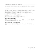
If
y
ou
can't
iden
tify
the
faulty
assem
bly
using
the
in
ternal
tests,
y
ou
can
execute
the
external
tests
in
addition
to
the
in
ternal
tests.
These
external
tests
are
also
built-in
tests
and
10
tests
are
a
v
ailable
in
the
4395A
service
mo
de.
Refer
to
the
T
able
6-2
to
kno
w
whic
h
assem
bly
is
probable
faulty
and
should
b e
replaced.
T
o
execute
the
external
tests,
p erform
the
follo wing
pro cedures.
a.
Press
4
PRESET
5,
4
SYSTEM
5,
NNNNNNNNNNNNNNNNNNNNNNNNNNNNNNNNNNNNNNNNN
SERVICE
TESTS
.
Pressing
NNNNNNNNNNNNNNNNNNNNNNNNNNNNNNNNNNNNNNNNNNNN
EXTERNAL
TESTS
jumps
to
the
rst
test
external
test,
test:50
FR
ONT
P
ANEL
DIA
G.
b.
Select
the
test
using
the
RPG
knob,
4
*
5,
4
+
5
k
eys
or
ENTR
Y
k
eys.
c.
Press
NNNNNNNNNNNNNNNNNNNNNNNNNNNNNNNNNNNNNN
EXECUTE
TEST
to
execute
the
sp ecify
ed
test.
d.
W
ait
un
til
the
test
result,
P
ASS
or
F
AIL,
is
display
ed.
T
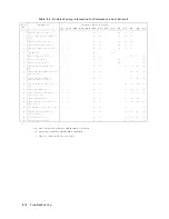
able
6-2.
Troubleshooting
Information
for
External
T
est
F
ailure
T
est
No.
F
ailed
T
est
Probable
F
aulty
Assembly
A1
A20
A30
A32
A33
A40
A50
A51
A2
A3
A5
A7
A8
A9
50
FRONT
P
ANEL
DIA
G
yy
y
y
51
DSK
DR
F
A
UL
T
ISOL'N
yy
y
y
52
24
BIT
I/O
POR
T
yy
y
y
53
NA
SR
C
TO
R
y
y
yy
y
yy
yy
yy
54
NA
SR
C
TO
A
y
y
yy
y
yy
yy
yy
55
NA
AR
RA
TIO
y
y
yy
y
yy
yy
yy
56
NA
SR
C
TO
B
y
y
yy
y
yy
yy
yy
57
NA
BR
RA
TIO
y
y
yy
y
yy
yy
yy
58
SA
LEVEL
y
y
y
yy
yy
yy
59
SA
PHASE
NOISE
y
y
yy
y
y
y
yy :
Most
suspicious
assembly
and
should
b
e
replaced.
y :
Suspicious
assembly
and
should
b
e
c
hecked.
6-8
Troubleshooting
Summary of Contents for 4395A
Page 10: ......
Page 26: ......
Page 34: ......
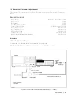
Page 77: ...Figure 2 17 B R Magnitude Ratio Phase Dynamic Accuracy Test Setup 2 Performance Tests 2 43 ...
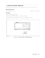
Page 167: ...Figure 5 1 Adjustment Hardware Setup Adjustments 5 5 ...
Page 186: ...Figure 5 13 Receiver Gain Adjustment Location 5 24 Adjustments ...
Page 190: ...Figure 5 16 Receiver Flatness Adjustment Setup 1 MHz 5 28 Adjustments ...
Page 194: ...Figure 5 20 DC Bias Adjustment Setup 2 5 32 Adjustments ...
Page 196: ...Figure 6 1 Troubleshooting Organization 6 2 Troubleshooting ...
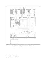
Page 206: ...Figure 7 1 Power Supply Lines Simplified Block Diagram 7 2 Power Supply Troubleshooting ...
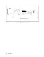
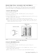
Page 212: ...Figure 7 5 A1 CPU Connector Locations 7 8 Power Supply Troubleshooting ...
Page 220: ...Figure 8 1 Digital Control Group Simplified Block Diagram 8 2 Digital Control Troubleshooting ...
Page 240: ...Figure 10 1 Top View Major Assemblies 10 4 Replaceable Parts ...
Page 292: ...Table A 2 Manual Changes by Firmware Version Version Make Manual Changes A 2 Manual Changes ...
Page 308: ......
Page 311: ...Figure B 1 Power Cable Supplied Power Requirement B 3 ...
Page 312: ......
Page 342: ......


