


FIND
OUT
WHY
THE
A50
SHUTDO
WN
LED
IS
OFF
Use
this
pro cedure
when
the
fan
is
rotating.
If
the
fan
is
not
rotating,
see
the
FIND
OUT
WHY
THE
F
AN
IS
NOT
R
OT
A
TING
.
If
the
fan
is
rotating
and
the
A50
SHUTDO
WN
LED
is
o,
the
problem
may
b e
in
the
A50
DC-DC
Con
v
erter
and
an
y
of
assem
blies
obtaining
the
p o
w
er
from
+5
VD
supply
and
the
higher
p o
w
er
supplies.
1.
Disconnect
the
Cable
from
the
A1J10
T
urn
the
analyzer
p o
w
er
o.
Disconnect
the
cable
from
A1J10.
T
urn
the
analyzer
p o
w
er
on.
If
the
A50
SHUTDO
WN
LED
go
es
on,
replace
the
A1
CPU.
If
the
A50
SHUTDO
WN
LED
is
still
o,
the
A1
CPU
is
v
eried.
T
urn
the
analyzer
p o
w
er
o
and
reconnect
the
cable
to
the
A1J10.
Con
tinue
with
the
next
R
emove
Assemblies
.
2.
Remo
v
e
Assemblies
a.
T
urn
the
analyzer
p o
w
er
o.
b.
Remo
v
e
the
assem
blies,
A2,
A3,
A5,
A7,
A8
and
A51.
c.
T
urn
the
analyzer
p o
w
er
on.
If
the
A50
SHUTDO
WN
LED
is
still
o,
insp ect
the
A20
motherb oard
for
soldering
bridges
and
shorted
traces
on
the
F
AN
PO
WER
and
the
F
AN
LOCK
signal
paths.
If
the
A50
SHUTDO
WN
LED
go
es
on,
the
A20
motherb oard
are
v
eried.
Con
tinue
with
the
next
step.
d.
Reinstall
eac
h
assem
bly
one
at
a
time.
T
urn
the
analyzer
p o
w
er
on
after
eac
h
is
installed.
The
assem
bly
that
causes
the
A50
SHUTDO
WN
LED
to
go
o
is
the
most
probable
faulty
assem
bly
.
Replace
the
assem
bly
.
If
no
assem
bly
makes
the
A50
SHUTDO
WN
LED
o,
con
tinue
with
the
next
Disc
onne
ct
the
Cable
fr
om
the
A9J2
.
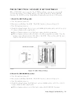
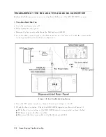
3.
Disconnect
the
Cable
from
the
A9J2
T
urn
the
analyzer
p o
w
er
o
and
reinstall
all
of
assem
blies.
Disconnect
the
cable
from
the
A9J2
and
turn
the
analyzer
p o
w
er
on.
The
lo
cation
of
the
A9J2
is
sho
wn
in
the
Figure
7-5 .
If
the
A50
SHUTDO
WN
LED
go
es
o,
the
A9
is
faulty
.
Replace
the
A9
assem
bly
.
P
o
w
er
Supply
Troubleshooting
7-7
Summary of Contents for 4395A
Page 10: ......
Page 26: ......
Page 34: ......
Page 77: ...Figure 2 17 B R Magnitude Ratio Phase Dynamic Accuracy Test Setup 2 Performance Tests 2 43 ...
Page 167: ...Figure 5 1 Adjustment Hardware Setup Adjustments 5 5 ...
Page 186: ...Figure 5 13 Receiver Gain Adjustment Location 5 24 Adjustments ...
Page 190: ...Figure 5 16 Receiver Flatness Adjustment Setup 1 MHz 5 28 Adjustments ...
Page 194: ...Figure 5 20 DC Bias Adjustment Setup 2 5 32 Adjustments ...
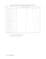
Page 196: ...Figure 6 1 Troubleshooting Organization 6 2 Troubleshooting ...
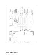
Page 206: ...Figure 7 1 Power Supply Lines Simplified Block Diagram 7 2 Power Supply Troubleshooting ...
Page 212: ...Figure 7 5 A1 CPU Connector Locations 7 8 Power Supply Troubleshooting ...
Page 220: ...Figure 8 1 Digital Control Group Simplified Block Diagram 8 2 Digital Control Troubleshooting ...
Page 240: ...Figure 10 1 Top View Major Assemblies 10 4 Replaceable Parts ...
Page 292: ...Table A 2 Manual Changes by Firmware Version Version Make Manual Changes A 2 Manual Changes ...
Page 308: ......
Page 311: ...Figure B 1 Power Cable Supplied Power Requirement B 3 ...
Page 312: ......
Page 342: ......


