


Exchange
Assemblies
Under
the
rebuilt-exc
hange
assem
bly
program,
certain
factory-repaired
and
tested
assem
blies
are
a
v
ailable
on
a
trade-in
basis.
These
assem
blies
are
oered
at
low
er
cost
than
a
new
assem
bly
while
meeting
all
of
the
factory
sp ecications
required
of
a
new
assem
bly
.
Replaceable
P
arts
List
Replaceable
parts
tables
list
the
follo wing
information
for
eac
h
part.
1
Agilent
T
ec
hnologies
part
n
um
b er.
2
P
art
n
um
b er
c
hec
k
digit
(CD).
3
P
art
quan
tit
y
as
sho
wn
in
the
corresp onding
gure.
There
may
or
may
not
b e
more
of
the
same
part
lo
cated
elsewhere
in
the
instrumen
t.
4
P
art
description,
using
abbreviations
(see
T
able
10-2).
5
A
t
ypical
manufacturer
of
the
part
in
a
v
e-digit
co de
(see
T
able
10-1 ).
6
The
manufacturer's
part
n
um
b er.
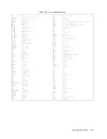
T
able
10-1.
Manufacturers
Code
List
Mfr
#
Name
Lo cation
Zip co de
00779
AMP
INC
HARRISBUR
G
P
A
US
17111
06369
HIR
OSE
ELECTRIC
CO
JP
06691
HOUSE
OF
METRICS
L
TD
SPRING
V
ALLEY
NY
US
10977
08747
KIT
A
GA
W
A
K
OGYO
TOKYO
JP
09635
T
AJIMI
MUSEN
TOKYO
JP
10572
XICOR
INC
MILPIT
AS
CA
12085
SCHLEGEL
CORP
R
OCHESTER
NY
US
14692
13160
TEA
C
OF
AMERICA
INC
MONTEBELLO
CA
US
90640
28480
A
GILENT
TECHNOLOGIES
CO
CORPORA
TE
HQ
P
ALO
AL
TO
CA
US
94304
28520
HEYCO
MOLDED
PR
ODUCTS
KENTW
OR
TH
NJ
US
07033
73734
FEDERAL
SCREW
PR
ODUCTS
CO
CHICA
GO
IL
US
60618
76381
3M
CO
ST
P
A
UL
MN
US
55144
78189
ILLINOIS
TOOL
W
ORKS
INC
SHAKEPR
OOF
ELGIN
IL
US
60126
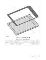
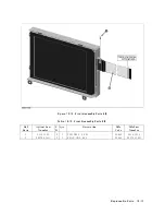
10-2
Replaceable
P
arts
Summary of Contents for 4395A
Page 10: ......
Page 26: ......
Page 34: ......
Page 77: ...Figure 2 17 B R Magnitude Ratio Phase Dynamic Accuracy Test Setup 2 Performance Tests 2 43 ...
Page 167: ...Figure 5 1 Adjustment Hardware Setup Adjustments 5 5 ...
Page 186: ...Figure 5 13 Receiver Gain Adjustment Location 5 24 Adjustments ...
Page 190: ...Figure 5 16 Receiver Flatness Adjustment Setup 1 MHz 5 28 Adjustments ...
Page 194: ...Figure 5 20 DC Bias Adjustment Setup 2 5 32 Adjustments ...
Page 196: ...Figure 6 1 Troubleshooting Organization 6 2 Troubleshooting ...
Page 206: ...Figure 7 1 Power Supply Lines Simplified Block Diagram 7 2 Power Supply Troubleshooting ...
Page 212: ...Figure 7 5 A1 CPU Connector Locations 7 8 Power Supply Troubleshooting ...
Page 220: ...Figure 8 1 Digital Control Group Simplified Block Diagram 8 2 Digital Control Troubleshooting ...
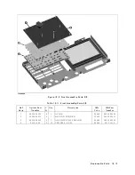
Page 240: ...Figure 10 1 Top View Major Assemblies 10 4 Replaceable Parts ...
Page 292: ...Table A 2 Manual Changes by Firmware Version Version Make Manual Changes A 2 Manual Changes ...
Page 308: ......
Page 311: ...Figure B 1 Power Cable Supplied Power Requirement B 3 ...
Page 312: ......
Page 342: ......


