


7
P
o
w
er
Supply
Troubleshooting
INTRODUCTION
Use
this
pro cedure
only
if
y
ou
ha
v
e
read
T
r
oublesho
oting
,
and
y
ou
b elieve
the
problem
is
in
the
p o
w
er
supply
.
The
pro cedure
is
designed
to
let
y
ou
iden
tify
the
bad
assem
bly
within
the
p o
w
er
supply
functional
group
in
the
shortest
p ossible
time.
The
p o
w
er
supply
functional
group
consists
of:
A40
Pre-Regulator
A50
DC-DC
Con
v
erter
All
assem
blies,
ho
w
ev
er,
are
related
to
the
p o
w
er
supply
functional
group
b ecause
p o
w
er
is
supplied
to
eac
h
assem
bly
.
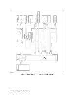
Figure
7-1
sho
ws
all
p o
w
er
lines
in
simplied
blo
c
k
diagram
form.
If
an
assem
bly
is
replaced,
see
Post
R
ep
air
Pr
o
c
e
dur
es
in
the
Post
R
ep
air
Pr
o
c
e
dur
es
c
hapter
in
this
man
ual.
It
tells
what
additional
tests
or
adjustmen
ts
need
to
b e
done
after
replacing
an
y
assem
bly
.
P
o
w
er
Supply
Troubleshooting
7-1
Summary of Contents for 4395A
Page 10: ......
Page 26: ......
Page 34: ......
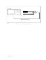
Page 77: ...Figure 2 17 B R Magnitude Ratio Phase Dynamic Accuracy Test Setup 2 Performance Tests 2 43 ...
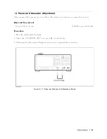
Page 167: ...Figure 5 1 Adjustment Hardware Setup Adjustments 5 5 ...
Page 186: ...Figure 5 13 Receiver Gain Adjustment Location 5 24 Adjustments ...
Page 190: ...Figure 5 16 Receiver Flatness Adjustment Setup 1 MHz 5 28 Adjustments ...
Page 194: ...Figure 5 20 DC Bias Adjustment Setup 2 5 32 Adjustments ...
Page 196: ...Figure 6 1 Troubleshooting Organization 6 2 Troubleshooting ...
Page 206: ...Figure 7 1 Power Supply Lines Simplified Block Diagram 7 2 Power Supply Troubleshooting ...
Page 212: ...Figure 7 5 A1 CPU Connector Locations 7 8 Power Supply Troubleshooting ...
Page 220: ...Figure 8 1 Digital Control Group Simplified Block Diagram 8 2 Digital Control Troubleshooting ...
Page 240: ...Figure 10 1 Top View Major Assemblies 10 4 Replaceable Parts ...
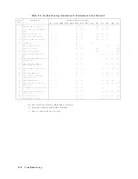
Page 292: ...Table A 2 Manual Changes by Firmware Version Version Make Manual Changes A 2 Manual Changes ...
Page 308: ......
Page 311: ...Figure B 1 Power Cable Supplied Power Requirement B 3 ...
Page 312: ......
Page 342: ......


