


5
Adjustments
Introduction
This
section
describ es
the
Adjustmen
ts
required
for
the
4395A
to
op erate
within
its
sp ecications.
These
adjustmen
ts
should
b e
p erformed
along
with
p erio
dic
maintenance
to
k
eep
the
4395A
in
optimum
op erating
condition.
The
recommended
calibration
p erio
d
is
12
mon
ths.
If
prop er
p erformance
cannot
b e
ac
hiev
ed
after
the
Adjustmen
ts,
see
the
T
roublesho oting
c
hapter.
Note
T
o
ensure
prop er
results
and
correct
instrumen
t
op eration,
Agilent
T
ec
hnologies
suggests
a
30
min
ute
w
arm-up
and
stabilization
p erio
d
b efore
p erforming
an
y
of
the
following
Adjustmen
ts.
Safety
Considerations
This
man
ual
con
tains
NOTEs,
CA
UTIONs,
and
W
ARNINGs
whic
h
m
ust
b e
follow
ed
to
ensure
the
safety
of
the
op erator
and
to
k
eep
the
instrumen
t
in
a
safe
and
serviceable
condition.
The
adjustmen
ts
m
ust
b e
p erformed
b
y
qualied
service
p ersonnel.
W
arning
Any
interruption
of
the
protectiv
e
ground
conductor
(inside
or
outside
the
instrument)
or
disconnection
of
the
protectiv
e
ground
terminal
can
mak
e
the
instrument
dangerous.
Intentional
interruption
of
the
protectiv
e
ground
system
for
any
reason
is
prohibited.
Remem
b er
that
the
capacitors
in
the
analyzer
can
remain
c
harged
for
sev
eral
min
utes,
ev
en
through
y
ou
ha
v
e
turned
the
analyzer
OFF
and
unplugged
it.
W
arning
The
adjustments
described
in
this
chapter
are
performed
with
po
w
er
applied
and
the
protectiv
e
co
v
ers
remo
v
ed.
Dangerous
v
oltage
lev
els
exist
at
many
points
and
can
result
in
serious
personal
injury
or
death
if
y
ou
come
into
contact
with
them.
Adjustments
5-1
Summary of Contents for 4395A
Page 10: ......
Page 26: ......
Page 34: ......
Page 77: ...Figure 2 17 B R Magnitude Ratio Phase Dynamic Accuracy Test Setup 2 Performance Tests 2 43 ...
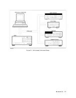
Page 167: ...Figure 5 1 Adjustment Hardware Setup Adjustments 5 5 ...
Page 186: ...Figure 5 13 Receiver Gain Adjustment Location 5 24 Adjustments ...
Page 190: ...Figure 5 16 Receiver Flatness Adjustment Setup 1 MHz 5 28 Adjustments ...
Page 194: ...Figure 5 20 DC Bias Adjustment Setup 2 5 32 Adjustments ...
Page 196: ...Figure 6 1 Troubleshooting Organization 6 2 Troubleshooting ...
Page 206: ...Figure 7 1 Power Supply Lines Simplified Block Diagram 7 2 Power Supply Troubleshooting ...
Page 212: ...Figure 7 5 A1 CPU Connector Locations 7 8 Power Supply Troubleshooting ...
Page 220: ...Figure 8 1 Digital Control Group Simplified Block Diagram 8 2 Digital Control Troubleshooting ...
Page 240: ...Figure 10 1 Top View Major Assemblies 10 4 Replaceable Parts ...
Page 292: ...Table A 2 Manual Changes by Firmware Version Version Make Manual Changes A 2 Manual Changes ...
Page 308: ......
Page 311: ...Figure B 1 Power Cable Supplied Power Requirement B 3 ...
Page 312: ......
Page 342: ......


