


Error
Messages
in
Alphabetical
Order
0123
Exp onen
t
to
o
large
The
magnitude
of
the
exp onent
w
as
larger
than
32000
(see
IEEE
488.2,
7.7.2.4.1).
F
0257
File
name
error
Indicates
that
a
legal
program
command
or
query
could
not
b e
executed
b ecause
the
le
name
on
the
device
media
w
as
in
error.
F
or
example,
an
attempt
w
as
made
to
cop
y
to
a
duplicate
le
name.
The
denition
of
what
constitutes
a
le
name
error
is
device-sp
ecic.
0256
File
name
not
found
A
legal
program
command
could
not
b e
executed
b ecause
the
le
name
on
the
device
media
w
as
not
found:
for
example,
an
attempt
w
as
made
to
read
or
cop
y
a
nonexisten
t
le.
143
FLO
A
TING
POINT
ERR
OR
OCCURED
Indicate
that
a
oating
p oint
error
o ccured
in
the
analyzer.
Data
pro cessing
may
not
b e
correct.
This
error
message
is
used
when
an
in
ternal
application
w
as
executed
for
illegal
data
sen
t
from
an
external
device,
or
when
an
in
ternal
softw
are
bug
w
as
detected.
Con
tact
y
our
nearest
Agilent
T
ec
hnologies
oce.
83
FORMA
T
NOT
V
ALID
FOR
MEASUREMENT
The
con
v
ersion
function
except
the
1/S
and
the
m
ultiple
phase
mo
des
is
not
v
alid
for
the
Smith,
admittance,
and
SWR
formats.
131
FREQUENCY
SWEEP
ONL
Y
The
sw
eep
t
yp e
m
ust
b e
frequency
sw
eep
when
the
cen
ter
step
size
is
set.
G
0105
GET
not
allow
ed
A
Group
Execute
T
rigger
(GET)
w
as
receiv
ed
within
a
program
message
(see
IEEE
488.2,
7.7).
H
0240
Hardw
are
error
Indicates
that
a
legal
program
command
or
query
could
not
b e
executed
b ecause
of
a
hardw
are
problem
in
the
analyzer.
Denition
of
what
constitutes
a
hard
w
are
problem
is
completely
device-sp ecic.
This
error
message
is
used
when
the
analyzer
cannot
detect
the
more
sp ecic
errors
describ ed
for
errors
0241
through
0249.
Messages-6
Summary of Contents for 4395A
Page 10: ......
Page 26: ......
Page 34: ......
Page 77: ...Figure 2 17 B R Magnitude Ratio Phase Dynamic Accuracy Test Setup 2 Performance Tests 2 43 ...
Page 167: ...Figure 5 1 Adjustment Hardware Setup Adjustments 5 5 ...
Page 186: ...Figure 5 13 Receiver Gain Adjustment Location 5 24 Adjustments ...
Page 190: ...Figure 5 16 Receiver Flatness Adjustment Setup 1 MHz 5 28 Adjustments ...
Page 194: ...Figure 5 20 DC Bias Adjustment Setup 2 5 32 Adjustments ...
Page 196: ...Figure 6 1 Troubleshooting Organization 6 2 Troubleshooting ...
Page 206: ...Figure 7 1 Power Supply Lines Simplified Block Diagram 7 2 Power Supply Troubleshooting ...
Page 212: ...Figure 7 5 A1 CPU Connector Locations 7 8 Power Supply Troubleshooting ...
Page 220: ...Figure 8 1 Digital Control Group Simplified Block Diagram 8 2 Digital Control Troubleshooting ...
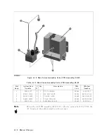
Page 240: ...Figure 10 1 Top View Major Assemblies 10 4 Replaceable Parts ...
Page 292: ...Table A 2 Manual Changes by Firmware Version Version Make Manual Changes A 2 Manual Changes ...
Page 308: ......
Page 311: ...Figure B 1 Power Cable Supplied Power Requirement B 3 ...
Page 312: ......
Page 342: ......


