


Error
Messages
in
Alphabetical
Order
0222
Data
out
of
range
A
legal
program
data
elemen
t
w
as
parsed
but
could
not
b e
executed
b ecause
the
in
terpreted
v
alue
w
as
outside
the
legal
range
as
dened
b
y
the
analyzer
(see
IEEE
488.2,
11.5.1.1.5).
0231
Data
questionable
Indicates
that
measuremen
t
accuracy
is
susp ect.
0104
Data
t
yp e
error
The
parser
recognized
an
unallow
ed
data
elemen
t.
F
or
example,
n
umeric
or
string
data
w
as
exp ected
but
blo
c
k
data
w
as
encoun
tered.
137
DC
CURRENT
LIMIT
OCCURED
The
output
curren
t
at
DC
SOUR
CE
p ort
is
reac
hed
to
an
upp er
limit
and
the
output
v
oltage
is
reduced
so
that
the
curren
t
do es
not
exceed
the
upp er
limit.
This
message
app ears
when
the
DC
SOUR
CE
p ort
is
used
in
v
oltage
con
trol
mo
de.
136
DC
SOUR
CE
O
VERLO
AD
The
DC
SOUR
CE
output
is
o
v
erlo ded.
138
DC
V
OL
T
A
GE
LIMIT
OCCURED
The
output
v
oltage
at
DC
SOUR
CE
p ort
is
reac
hed
to
an
upp er
limit
and
the
output
curren
t
is
reduced
so
that
the
v
oltage
do es
not
exceed
the
upp er
limit.
This
message
app ears
when
the
DC
SOUR
CE
p ort
is
used
in
curren
t
con
trol
mo
de.
37
DISPLA
Y
BUFFER
IS
FULL
The
display
buer
is
lled
with
the
o
v
erlay
traces
or
traces
dra
wn
b
y
IBASIC
DRA
W/MOVE
commands,
etc.
117
DUPLICA
TE
FILE
EXTENSION
The
extension
name
en
tered
is
already
used
for
other
le
t
yp es.
Use
other
extension
name.
E
15
EX
CEEDED
7
ST
AND
ARDS
PER
CLASS
A
maximum
of
sev
en
standards
can
b e
dened
for
an
y
class.
0200
Execution
error
This
is
the
generic
syn
tax
error
that
the
analyzer
cannot
detect
more
sp ecic
errors.
This
co de
indicates
only
that
an
execution
error
as
dened
in
IEEE
488.2,
11.5.1.1.5
has
o ccurred.
Messages-5
Summary of Contents for 4395A
Page 10: ......
Page 26: ......
Page 34: ......
Page 77: ...Figure 2 17 B R Magnitude Ratio Phase Dynamic Accuracy Test Setup 2 Performance Tests 2 43 ...
Page 167: ...Figure 5 1 Adjustment Hardware Setup Adjustments 5 5 ...
Page 186: ...Figure 5 13 Receiver Gain Adjustment Location 5 24 Adjustments ...
Page 190: ...Figure 5 16 Receiver Flatness Adjustment Setup 1 MHz 5 28 Adjustments ...
Page 194: ...Figure 5 20 DC Bias Adjustment Setup 2 5 32 Adjustments ...
Page 196: ...Figure 6 1 Troubleshooting Organization 6 2 Troubleshooting ...
Page 206: ...Figure 7 1 Power Supply Lines Simplified Block Diagram 7 2 Power Supply Troubleshooting ...
Page 212: ...Figure 7 5 A1 CPU Connector Locations 7 8 Power Supply Troubleshooting ...
Page 220: ...Figure 8 1 Digital Control Group Simplified Block Diagram 8 2 Digital Control Troubleshooting ...
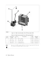
Page 240: ...Figure 10 1 Top View Major Assemblies 10 4 Replaceable Parts ...
Page 292: ...Table A 2 Manual Changes by Firmware Version Version Make Manual Changes A 2 Manual Changes ...
Page 308: ......
Page 311: ...Figure B 1 Power Cable Supplied Power Requirement B 3 ...
Page 312: ......
Page 342: ......


