


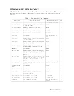


T
able
1-2.
Recommended
T
est
Equipment
(continued)
Equipmen t
Critical
Sp
ecications
Recommended
Mo del/
Agilen
t
P
art
Numb
er
Qty
6
dB
Fixed
A
tten uation
50
,
N(m)-N(f
)
8491A
Opt.
006
2
6
dB
Fixed
A
tten uation
50
,
N(m)-N(f
),
VSWR
1.015
8491A
Opt.
006
&
Opt.
H60
7
2
10
dB
Fixed
A
tten uation
50
,
N(m)-N(f
),
VSWR
1.015
8491A
Opt.
010
&
Opt.
H60
8
1
Tw
o-W
ay
P
ow
er
Splitter
F
requency
Range:
100
kHz
to
500
MHz,
Output
T
racking:
0.15
dB
11667A
1
Cables
T
yp
e-N
cable,
50
11500B
or
part
of
11851B
9
4
BNC
cable,
61
cm,
50
PN
8120-1839
2
BNC
cable,
122
cm,
50
PN
8120-1840
2
Adapters
BNC(f
)-BNC(f
)
adapter,
50
PN
1250-0080
1
T
ee
BNC(m)-(f
)-(f
)
adapter,
50
PN
1250-0781
1
BNC(f
)-Dual
Banana
Plug
Adapter,
50
PN
1251-2277
1
N(m)-N(m)
adapter,
50
PN
1250-1475
1
N(m)-BNC(f
)
adapter,
50
PN
1250-0780
2
APC7.5-N(f
)
adapter,
50
11524A
or
part
of
85032B
10
1
1:
Option
001
(optional
time
base)
is
not
required,
when
a
frequency
standard
in
T
able
1-2
is
av
ailable.
2:
Required
for
testing
an
analyzer
equipp
ed
with
Option
1D5
(High
Stabilit y
F
requency
Reference).
3:
Calibration
v
alues
at
50
MHz
are
required
in
the
tests.
See
the
Calibr
ation
Data
R
e
quir
e
d
for
Step
A
ttenuators
later
in
this
c
hapter.
4:
An
8496G
step
attenuator
with
required
low
VSWR
(
1.02)
can
b
e
purc hased
by
sp
ecifying
option
H60.
5:
Required
when
an
8496G
step
atten uator
is
used
in
the
tests.
6:
The
85032B
includes
a
t
yp
e-N(m)
50
termination.
7:
An
8491A
Opt.
006
xed
attenuator
with
required
low
VSWR
(
1.015)
can
b
e
purc hased
by
sp
ecifying
Opt.
H60.
8:
An
8491A
Opt.
010
xed
attenuator
with
required
low
VSWR
(
1.015)
can
b
e
purc hased
by
sp
ecifying
Opt.
H60.
9:
The
11851B
includes
three
N(m)-N(m)
cables
of
61
cm
and
a
N(m)-N(m)
cable
of
88
cm.
10:
The
85032B
includes
t
w
o
APC7.5-N(f
)
adapters.
Calibration
Data
Required
for
Step
A
ttenuator
The
four
p erformance
tests
listed
b elow
measure
the
analyzer's
p erformance
against
a
kno
wn
standard
(the
attenuation
v
alues
at
a
frequency
50
MHz
of
the
8496G
Opt.
001
and
H60
step
attenuators).
3.
Non-Sw
eep
P
o
w
er
Linearity
T
est
11.
Magnitude
Ratio/Phase
Dynamic
Accuracy
T
est
14.
Amplitude
Fidelit
y
T
est
15.
Input
A
tten
uator
Switching
Uncertain
t
y
T
est
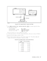
These
tests
require
the
calibrated
v
alues
of
the
attenuators
listed
in
T
able
1-3 .
The
attenuation
v
alues
(referenced
to
0
dB
setting)
are
required
in
the
calculation
sheet.
The
attenuation
v
alues
used
in
the
tests
are
listed
in
eac
h
calculation
sheet.
1-6
General
Information
Summary of Contents for 4395A
Page 10: ......
Page 26: ......
Page 34: ......
Page 77: ...Figure 2 17 B R Magnitude Ratio Phase Dynamic Accuracy Test Setup 2 Performance Tests 2 43 ...
Page 167: ...Figure 5 1 Adjustment Hardware Setup Adjustments 5 5 ...
Page 186: ...Figure 5 13 Receiver Gain Adjustment Location 5 24 Adjustments ...
Page 190: ...Figure 5 16 Receiver Flatness Adjustment Setup 1 MHz 5 28 Adjustments ...
Page 194: ...Figure 5 20 DC Bias Adjustment Setup 2 5 32 Adjustments ...
Page 196: ...Figure 6 1 Troubleshooting Organization 6 2 Troubleshooting ...
Page 206: ...Figure 7 1 Power Supply Lines Simplified Block Diagram 7 2 Power Supply Troubleshooting ...
Page 212: ...Figure 7 5 A1 CPU Connector Locations 7 8 Power Supply Troubleshooting ...
Page 220: ...Figure 8 1 Digital Control Group Simplified Block Diagram 8 2 Digital Control Troubleshooting ...
Page 240: ...Figure 10 1 Top View Major Assemblies 10 4 Replaceable Parts ...
Page 292: ...Table A 2 Manual Changes by Firmware Version Version Make Manual Changes A 2 Manual Changes ...
Page 308: ......
Page 311: ...Figure B 1 Power Cable Supplied Power Requirement B 3 ...
Page 312: ......
Page 342: ......


