


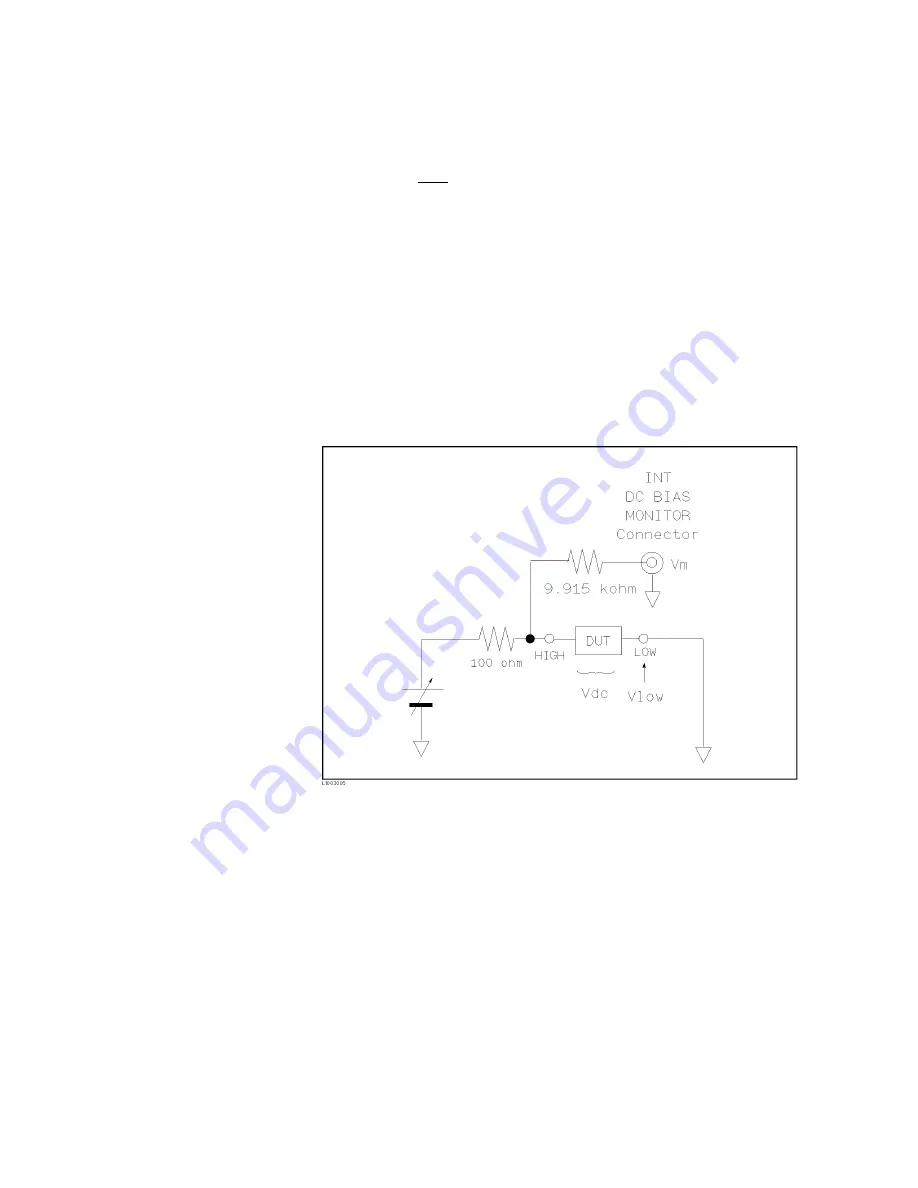
k)
in
series
b et
w
een
the
INT
DC
BIAS
MONITOR
connector
and
the
H
CUR
T
erminal.
So
if
y
ou
use
a
dc
v
oltmeter
to
nd
the
actual
DC
bias
v
oltage,
use
the
following
formula
to
calculate
it.
V
dc
=
(1
+
9 : 9 k
R
in
)
2
V
m
0
V
l ow
Where,
V
dc
:
Actual
DC
bias
v
oltage
R
in
:
Input
Resistor
of
the
DC
v
oltage
meter
V
m
:
Actual
monitor
v
alue
at
the
INT
DC
BIAS
MONITOR
connector
V
low
:
Residual
v
oltage
at
the
LO
W
T
erminal
(Typical:
2
mV,
Max.:
6
mV
(DCI:ISO
ON),
20
mV
(DCI:ISO
OFF))
Figure
3-7.
DC
BIAS
Monitor
Circuits
Front
P
anel
Operation
for
Setting
the
DC
Bias
There
are
t
w
o
w
a
ys
to
set
the
DC
bias,
one
is
to
use
the
softkeys,
and
the
other
is
to
use
the
n
umeric
en
try
k
eys.
P
erform
the
follo wing
steps
to
set
the
DC
bias.
1.
Mov
e
the
cursor
to
the
BIAS
eld.
The
follo wing
softkeys
will
b e
display
ed.
a.
NNNNNNNNNNNNNNNNNNNN
INCR
*
Press
this
softkey
to
increase
the
DC
bias
lev
el.
b.
NNNNNNNNNNNNNNNNNNNN
DECR
+
Press
this
softkey
to
decrease
the
DC
bias
lev
el.
3-16
DISPLA
Y
F
ORMA
T
Menu
Summary of Contents for 4284A
Page 12: ......
Page 37: ...Figure 1 1 Power Cable Supplied Installation and Set Up Guide 1 3 ...
Page 54: ...Figure 2 5 Display Pages 1 3 2 12 Overview ...
Page 55: ...Figure 2 5 Display Pages 2 3 Overview 2 13 ...
Page 56: ...Figure 2 5 Display Pages 3 3 2 14 Overview ...
Page 58: ...Figure 2 7 Softkey Selection Example 2 16 Overview ...
Page 60: ...Figure 3 1 Available Fields on the MEAS DISPLAY Page 3 2 DISPLAY FORMAT Menu ...
Page 61: ...Figure 3 2 Available Softkeys on the MEAS DISPLAY Page DISPLAY FORMAT Menu 3 3 ...
Page 66: ...Figure 3 4 Effective Measuring Range Oscillator Level 2V or 20 mA 3 8 DISPLAY FORMAT Menu ...
Page 91: ...Figure 3 15 Available Fields on the LIST SWEEP DISPLAY Page DISPLAY FORMAT Menu 3 33 ...
Page 96: ......
Page 99: ...Figure 4 2 Available Softkeys on the MEAS SETUP Page MEAS SETUP Menu 4 3 ...
Page 104: ...Figure 4 5 Available Operating Area for the ALC Function 4 8 MEAS SETUP Menu ...
Page 113: ...4 Press NNNNNNNNNNN YES to reset the 4284A MEAS SETUP Menu 4 17 ...
Page 115: ...Figure 4 8 Available Fields on the CORRECTION Page MEAS SETUP Menu 4 19 ...
Page 116: ...Figure 4 9 Available Softkeys on the CORRECTION Page 4 20 MEAS SETUP Menu ...
Page 131: ...Figure 4 15 Available Fields on the LIMIT TABLE SETUP Page MEAS SETUP Menu 4 35 ...
Page 145: ...Figure 4 21 Available Fields on the LIST SWEEP SETUP Page MEAS SETUP Menu 4 49 ...
Page 152: ......
Page 158: ...Figure 5 4 Available Fields on the SYSTEM CONFIG Page 5 6 Catalog System Configuration ...
Page 228: ...Figure 7 19 Standard Event Status Register 7 28 Remote Control ...
Page 240: ......
Page 361: ...Caution The memory card should be removed before packing the 4284A General Information 9 29 ...
Page 362: ......
Page 432: ......
Page 436: ......
Page 440: ......
Page 460: ......


