


Printer
Function
P
erform
the
following
steps
to
prin
t
out
the
information
of
the
CORRECTION
page
using
the
DISP
mo
de.
1.
Connect
the
4284A
to
the
prin
ter
using
an
GPIB
cable.
2.
Set
the
prin
ter
to
the
Listen
Only
mo
de.
3.
Set
the
T
alk
Only
mo
de
to
ON
from
the
SYSTEM
CONFIG
page.
4.
Press
4
MEAS
SETUP
5,
and
NNNNNNNNNNNNNNNNNNNNNNNNNNNNNNNN
CORRECTION
to
display
the
CORRECTION
page.
5.
Mov
e
the
cursor
to
the
SYS
MENU
eld.
6.
Press
NNNNNNNNNNNNNNNNNNNNNNNNNNNNNNNN
DISP
to
prin
t
out
the
display
page.
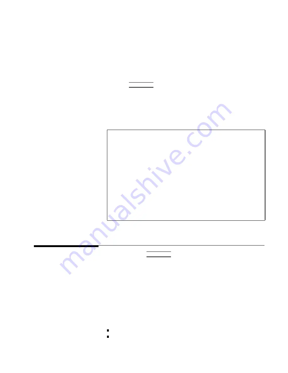
The
display
page
is
prin
ted
out
to
the
prin
ter
as
sho
wn
in
Figure
4-14.
<CORRECTION>
SYS
MENU
OPEN
:
ON
CABLE
:
0
m
SHORT:
ON
MODE
:
MULTI
LOAD
:
ON
CH
No.:
0
FUNC
:
Cp-D
FREQ1
:1.00000kHz
REF
A:
100.000pF
B:
.000000
MEA
A:
99.6222pF
B:
.008178
FREQ2
:2.00000kHz
REF
A:
100.000pF
B:
.000000
MEA
A:
99.8350pF
B:
.003234
FREQ2
:1.00000MHz
REF
A:
100.000pF
B:
.000003
MEA
A:
99.9439pF
B:
.000266
Figure
4-14.
CORRECTION
P
age
Example
LIMIT
T
ABLE
SETUP
P
age
When
y
ou
press
4
MEAS
SETUP
5,
and
NNNNNNNNNNNNNNNNNNNNNNNNNNNNNNNNNNN
LIMIT
TABLE
,
the
LIMIT
T
ABLE
SETUP
page
will
b e
display
ed.
The
LIMIT
T
ABLE
SETUP
page
allo ws
y
ou
to
set
the
4284A's
comparator.
The
4284A's
built-in
comparator
can
sort
devices
in
to
a
maximum
of
ten
bins
(BIN
1
to
BIN
9
and
one
OUT
OF
BINS)
using
a
maxim
um
of
nine
pairs
of
primary
limits
and
one
pair
of
secondary
parameter
limits.
Also,
devices
whose
primary
parameter
is
within
limits,
but
whose
secondary
parameter
measuremen
t
result
not
within
limits,
can
b e
sorted
in
to
an
A
UXiliary
BIN.
The
comparator
function
is
esp ecially
useful
when
using
the
4284A
with
a
comp onen
t
handler
(handler
in
terface
option
is
installed).
These
limit
settings
for
bin
sorting
are
only
set
on
this
LIMIT
T
ABLE
SETUP
page.
Measuremen
t
F
unction
( FUNC
)
Comparator
F
unction's
Limit
Mo
de
( MODE
)
MEAS
SETUP
Menu
4-33
Summary of Contents for 4284A
Page 12: ......
Page 37: ...Figure 1 1 Power Cable Supplied Installation and Set Up Guide 1 3 ...
Page 54: ...Figure 2 5 Display Pages 1 3 2 12 Overview ...
Page 55: ...Figure 2 5 Display Pages 2 3 Overview 2 13 ...
Page 56: ...Figure 2 5 Display Pages 3 3 2 14 Overview ...
Page 58: ...Figure 2 7 Softkey Selection Example 2 16 Overview ...
Page 60: ...Figure 3 1 Available Fields on the MEAS DISPLAY Page 3 2 DISPLAY FORMAT Menu ...
Page 61: ...Figure 3 2 Available Softkeys on the MEAS DISPLAY Page DISPLAY FORMAT Menu 3 3 ...
Page 66: ...Figure 3 4 Effective Measuring Range Oscillator Level 2V or 20 mA 3 8 DISPLAY FORMAT Menu ...
Page 91: ...Figure 3 15 Available Fields on the LIST SWEEP DISPLAY Page DISPLAY FORMAT Menu 3 33 ...
Page 96: ......
Page 99: ...Figure 4 2 Available Softkeys on the MEAS SETUP Page MEAS SETUP Menu 4 3 ...
Page 104: ...Figure 4 5 Available Operating Area for the ALC Function 4 8 MEAS SETUP Menu ...
Page 113: ...4 Press NNNNNNNNNNN YES to reset the 4284A MEAS SETUP Menu 4 17 ...
Page 115: ...Figure 4 8 Available Fields on the CORRECTION Page MEAS SETUP Menu 4 19 ...
Page 116: ...Figure 4 9 Available Softkeys on the CORRECTION Page 4 20 MEAS SETUP Menu ...
Page 131: ...Figure 4 15 Available Fields on the LIMIT TABLE SETUP Page MEAS SETUP Menu 4 35 ...
Page 145: ...Figure 4 21 Available Fields on the LIST SWEEP SETUP Page MEAS SETUP Menu 4 49 ...
Page 152: ......
Page 158: ...Figure 5 4 Available Fields on the SYSTEM CONFIG Page 5 6 Catalog System Configuration ...
Page 228: ...Figure 7 19 Standard Event Status Register 7 28 Remote Control ...
Page 240: ......
Page 361: ...Caution The memory card should be removed before packing the 4284A General Information 9 29 ...
Page 362: ......
Page 432: ......
Page 436: ......
Page 440: ......
Page 460: ......


