Parameters and firmware blocks
162
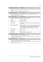
(5)
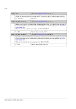
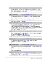
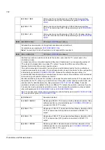
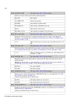
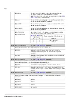
FEN-21 RES
Communication active. Module type: FEN-21 Resolver Interface.
Input: Resolver input (X52). See parameter group
(6)
FEN-21 TTL
Communication active. Module type: FEN-21 Resolver Interface.
Input: TTL encoder input (X51). See parameter group
(7)
FEN-31 HTL
Communication active. Module type: FEN-31 HTL Encoder Interface.
Input: HTL encoder input (X82). See parameter group
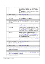
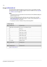
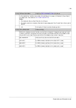
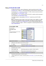
90.02
ENCODER 2 SEL
FW block:
(see above)
Activates the communication to the optional encoder/resolver interface 2.
For selections, see parameter
Note:
The counting of full shaft revolutions is not supported for encoder 2.
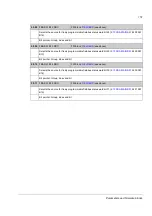
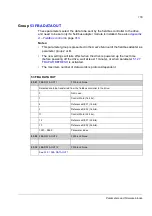
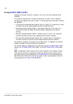
90.03
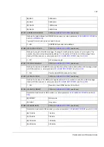
EMUL MODE SEL
FW block:
(see above)
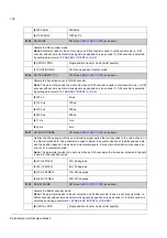
Enables the encoder emulation and selects the position value and the TTL output used in the
emulation process.
In encoder emulation a calculated position difference is transformed to a corresponding number of
TTL pulses to be transmitted via encoder TTL output. The position difference is the difference
between the latest and the previous position values.
The position value used in emulation can be either a position determined by the drive software or
a position measured by an encoder. If drive software position is used, the source for the used position
is selected by parameter
. Because the software causes a delay, it is
recommended that actual position is always taken from an encoder. Drive software is recommended
to be used only with position reference emulation.
Encoder emulation can be used to increase or decrease the pulse number when TTL encoder data is
transmitted via the TTL output e.g. to another drive. If the pulse number requires no alternation, use
encoder echo for data transformation. See parameter
Note:
If encoder
emulation and echo are enabled for the same FEN-xx TTL output, the emulation overrides the echo.
If an encoder input is selected as emulation source, the corresponding selection must be activated
either with parameter
The TTL encoder pulse number used in emulation must be defined by parameter
.
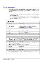
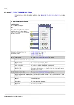
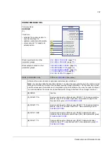
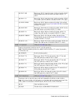
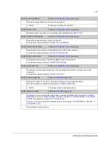
(0)
DISABLED
Emulation disabled.
(1)
FEN-01 SWREF
Module type: FEN-01 TTL Encoder interface Module. Emulation: Drive
software position (source selected by par.
emulated to FEN-01 TTL output.
(2)
FEN-01 TTL+
Module type: FEN-01 TTL Encoder interface Module. Emulation: FEN-
01 TTL encoder input (X32) position is emulated to FEN-01 TTL
output.
(3)
FEN-01 TTL
Module type: FEN-01 TTL Encoder interface Module. Emulation: FEN-
01 TTL encoder input (X31) position is emulated to FEN-01 TTL
output.
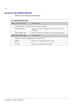
(4)
FEN-11 SWREF
Module type: FEN-11 Absolute Encoder Interface. Emulation: Drive
software position (source selected by par.
emulated to FEN-11 TTL output.
Summary of Contents for ACSM1 Series
Page 1: ...ACSM1 Firmware Manual ACSM1 Speed and Torque Control Program...
Page 2: ......
Page 4: ......
Page 12: ...Table of contents 12...
Page 49: ...Drive control and features 49...
Page 282: ...Standard function blocks 282...
Page 306: ...Application program template 306...
Page 312: ...Control chain block diagrams 312...
Page 331: ...331...
Page 332: ...332...
Page 333: ......

