


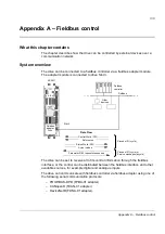


Appendix A – Fieldbus control
318
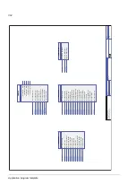
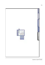
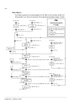
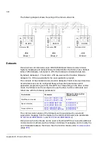
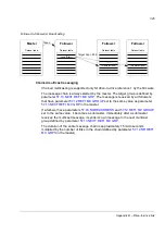
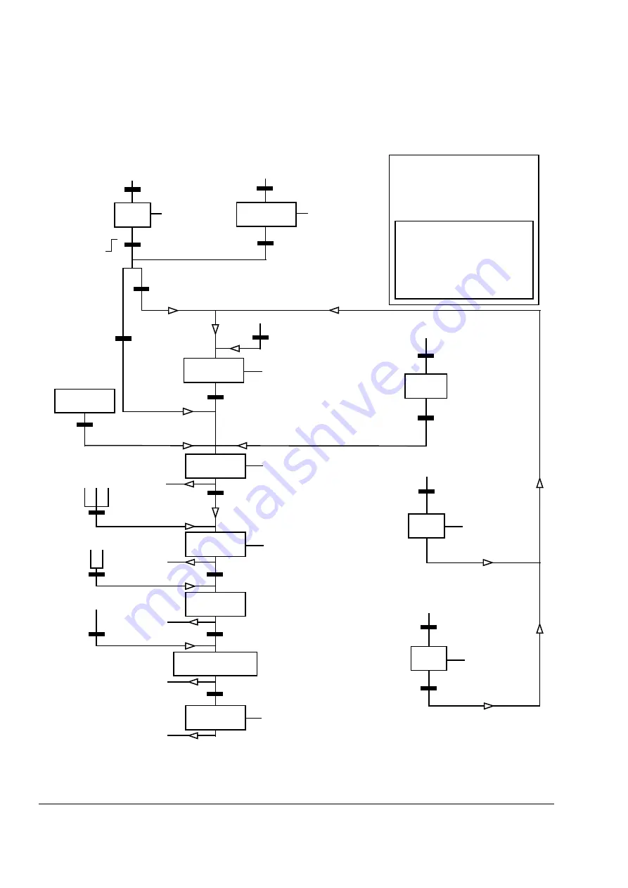
State diagram
The following presents the state diagram for the FBA communication profile. For
other profiles, see the
User’s Manual
of the appropriate fieldbus adapter module.
MAINS OFF
Power ON
from any state
FBA
Communication
Profile
(FBA SW Bit 0 = 1)
n(f)=0 / I=0
(FBA SW Bit 6 = 1)
(FBA CW Bit 16 = 1)
(FBA CW Bit 0 = 1)
OFF1
(FBA CW Bit 4 = 1
OFF1
ACTIVE
C D
(FBA CW Bit 13 = 0)
RUNNING
(FBA SW Bit 3 = 1)
(FBA SW Bit 5 = 1)
from any state
from any state
Emergency Stop
OFF3
(FBA CW Bit 3 = 1
n(f)=0 / I=0
OFF3
ACTIVE
Emergency OFF
OFF2
(FBA CW Bit 2 = 1
(FBA SW Bit 4 = 1)
OFF2
ACTIVE
RFG: OUTPUT
ENABLED
RFG: ACCELERATOR
ENABLED
B
B C D
(FBA CW Bit 12 = 0)
D
(FBA CW Bit 14 = 0)
A
C
FBA CW = Fieldbus Control Word
FBA SW = Fieldbus Status Word
n = Speed
I = Input Current
(FBA SW Bit 8 = 1)
RFG = Ramp Function Generator
f = Frequency
D
from any state
Fault
(FBA SW Bit 16 = 1)
(FBA CW Bit 8 = 1)
START
INHIBITED
(FBA CW Bits 7 = 1)
READY TO
START
Par. 10.12 = 0
from any state
and FBA CW Bit 0 = 1)
and FBA CW Bit 0 = 1)
and FBA CW Bit 0 = 1)
Par. 10.12 = 1
RUN
DISABLE
FAULT
OPERATING
(FBA SW Bit 1 = 0)
(FBA CW Bit 7 = 0)
(FBA CW = xxxx xxxx xxxx xxx
0
xxxx
1
xxx
1
xxx xx
10)
(FBA CW = xxxx xxxx xxxx xxx
0
xxx
0
1
xxx
1
xxx xx
10)
(FBA CW = xxxx xxxx xxxx xxx
0
xx
00
1
xxx
1
xxx xx
10)
(FBA CW = xxxx xxxx xxxx xxx
0
x
000
1
xxx
1
xxx xx
10)
E
E
Summary of Contents for ACSM1 Series
Page 1: ...ACSM1 Firmware Manual ACSM1 Speed and Torque Control Program...
Page 2: ......
Page 4: ......
Page 12: ...Table of contents 12...
Page 49: ...Drive control and features 49...
Page 282: ...Standard function blocks 282...
Page 306: ...Application program template 306...
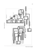
Page 312: ...Control chain block diagrams 312...
Page 331: ...331...
Page 332: ...332...
Page 333: ......