


2
1
3
4
5
6
7
8
9
10
11
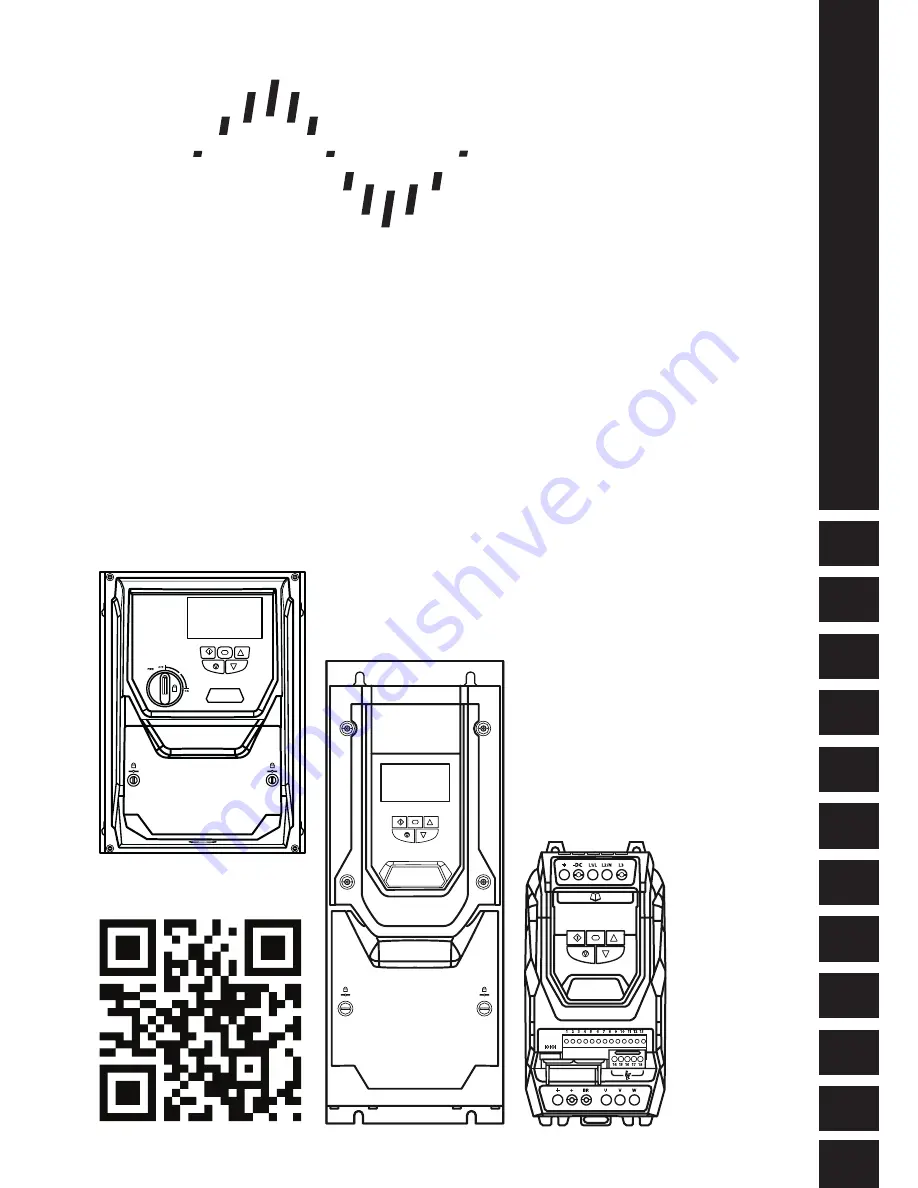
User Guide
AC Vector Drive
For Precision Industrial Motor Speed & Torque Control
0.75 - 160kW / 1HP - 250HP
200 - 480V 1 / 3 Phase Input
General Information
and Ratings
Quick Start Up
Mechanical Installation
Electrical Installation
Keypad and Display Operation
Parameters
Extended
Parameters
Serial
Communications
Control Terminal
Functions
Technical Data
Troubleshooting
P2 Series
Bardac
drives


