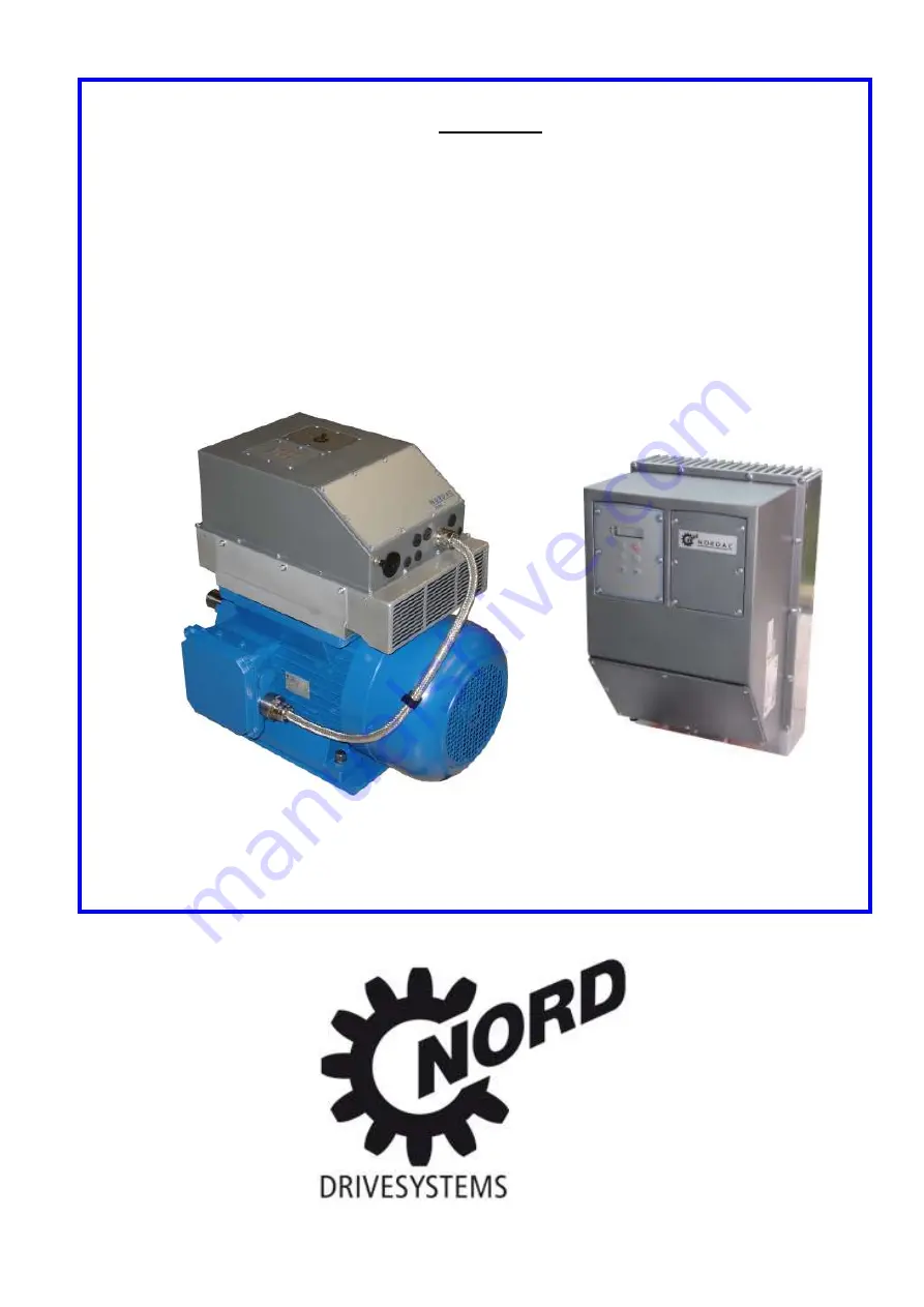
background image


MANUAL 


NORDAC SK 750E 

Frequency Inverter 


SK 750E-551-323-A (-W) ... SK 750E-112-323-A (-W)


(5.5kW … 11kW, 3~ 230V) 

SK 750E-551-340-A (-W) ... SK 750E-222-340-A (-W)


(5.5kW … 22kW, 3~ 400V) 


BU 0750 GB


Для


заказов

 : +7(499)707-11-20 Email: [email protected]

8-800-511-65-88 (

Бесплатно


по


РФ

)

Summary of Contents for SK 750E Series

Page 1: ...ORDAC SK 750E Frequency Inverter SK 750E 551 323 A W SK 750E 112 323 A W 5 5kW 11kW 3 230V SK 750E 551 340 A W SK 750E 222 340 A W 5 5kW 22kW 3 400V BU 0750 GB 7 499 707 11 20 Email i sp t ru 8 800 51...

Page 2: ...s and do not fail to observe them and to follow instructions 3 Transport storage Follow the instructions for transport storage and proper han dling Ensure climatic conditions as specified in prEN 5017...

Page 3: ...s to be satisfied fol lowing the Operating Instructions is indispensable So please read the Operating Instructions first before starting to work with the device The Operating Instructions contain impo...

Page 4: ...L2 L3 21 2 9 2 Electromagnetic brake Br Br PE 21 2 9 3 Braking resistor connection B B PE 21 2 9 4 Motor cable U V W PE 21 2 9 5 Temperature sensor T1 T2 22 2 9 6 Power supply terminals 22 2 9 7 Contr...

Page 5: ...Minimum configuration of the control terminals 77 7 PARAMETERISATION 78 7 1 Display of array parameters 79 7 2 Indication of operational values 80 7 3 Basic parameters 81 7 4 Motor data and characteri...

Page 6: ...oftware If a different soft ware version is stored on the frequency inverter used accordance with the manual may not always be en sured To be on the safe side the most recent manual should be download...

Page 7: ...additional module with R L switch and infinitely variable potentiometer SK TU2 PBR Profibus additional module for Profibus communication 1 5MBaud SK TU2 PBR 24V for external 24V supply 12MBaud SK TU2...

Page 8: ...utomatically when it is con nected to the mains The printed circuit boards carry highly sensitive MOS semiconductor components for which static elec tricity can be particularly harmful That is why you...

Page 9: ...steps to ensure effective noise suppression Using a line filter of the type recommended by the manufacturer would be such a suitable measure 1 5 Licenses and approvals 1 5 1 UL and cUL approvals For...

Page 10: ...rmation regarding mains voltage noise suppression filter type of protection and special design features if any of the device IMPORTANT Always refer to the nomenclature whenever placing an order or req...

Page 11: ...protection Both designs combination of inverter with motor installation close to the motor are available protected this way This type of protection al lows for the standard subassemblies used with the...

Page 12: ...ology Unit SK TU2 CTR SK TU2 POT Optional Technology Unit Bus subassemblies Optional custom interface SK CU1 Optional special extension SK XU1 If the SK 750E frequency inverter is designed for install...

Page 13: ...requency inverter and any components located above or below it so as to encourage the air to flow freely in between No gaps need however to be provided between devices when they are installed side by...

Page 14: ...it optional Section 2 5 Weight L1 W1 L2 SK 750E 551 323 A SK 750E 751 323 A 414 372 255 237 5 165 443 401 220 5 457 5 415 5 6 5 18 0 SK 750E 551 340 A SK 750E 152 340 A SK 750E 921 323 A SK 750E 112 3...

Page 15: ...red which can be ordered as accessory parts These retainers are screwed on to the back of the SK 750E with the attachment material supplied along with them Both wall mounting kits are in accordance wi...

Page 16: ...anual 16 Technical design subject to change BU 0750 GB 2 5 1 Dimensions of the SK 750E with wall mounting kit Note For the dimensions please read the table in Section 2 2 W1 W L L2 L1 Fig SK 750E with...

Page 17: ...ble al lowing for mounting the device to differently sized motors 132 160 180MX LX Attachment frame for device Piece number Attachm frame 750E BG1 IEC132 SK 750E 551 323 A SK 750E 751 323 A SK 750E 55...

Page 18: ...greater length of wire runs unshielded The shield of analogue setpoint cables should be connected to earth at the frequency inverter at one end only 4 When laying the wiring a certain distance should...

Page 19: ...of input voltage is disconnected before you establish connections to the unit or change them Make sure that both the frequency inverter and the motor are rated to match the connecting voltage Switchin...

Page 20: ...r a large part to the shield clamping device Note Shielded cables must absolutely be used to ensure the radio interference suppression levels specified see also Section 10 4 EMC limit value classes IM...

Page 21: ...energy is fed back to the inverter This could result in an overvoltage situation followed by automatic disconnection of the inverter To prevent this from happening a braking chopper is integrated in...

Page 22: ...revented by internal inverter control For more detailed informa tion see Section 8 Error signals Evaluation of temperature sensor data can also be ensured via any of the optional custom interfaces SK...

Page 23: ...ll screwdriver Maximum connection cross section 1 5mm 2 or 1 0mm 2 respectively AWG 26 14 or 26 16 resp depending on the option used Cables to be laid separately from mains motor cables and to be shie...

Page 24: ...al however with regard to the cable entries for the control level control of the brake resistor and the temperature sensor input Mains Brake resistor Line to motor RS485 interface connect SK PAR 2H Te...

Page 25: ...equency inverter externally where they are conven iently accessible They are designed for manual control or parameterization or to enable connection of the in verter to a bus system Customer Units SK...

Page 26: ...lBox simultane ously IMPORTANT While the SK TU2 technology units are available with the IP55 type of protection the SK TU2 C meet the requirements for IP66 Still the functionality and the dimensions o...

Page 27: ...le SK TU2 DEV Part no 275130090 IP55 With this interface the NORDAC SK 750E can be controlled via the serial DeviceNet port with the DeviceNet protocol DeviceNet interface Baud rate 500 Kbps One 5 pol...

Page 28: ...t the unit by pushing it lightly towards the assembly surface Make sure that the push lock strips make proper contact 4 Fix the 6 screws again IMPORTANT Operation not allowed unless an effective PE co...

Page 29: ...quency has been preset in parameter P113 the display alternates between 0 0Hz and the set ting made in P113 When the frequency inverter is enabled the display changes automatically to the operating va...

Page 30: ..._ _ LEDs 1 2 In the display mode the LEDs show the parameter set controlling current operation while in the parame terization mode they show the parameter set selected to be programmed In the latter c...

Page 31: ...the parame ter set is shown in a binary coded form By changing the setting in parameter P100 users may even switch from one parameter set to another without operation having to be interrupted control...

Page 32: ...face if it has operate the STOP button either of the value keys or can be used to to go directly from the mode where operating values are displayed to the parameterisation mode P 0 _ _ P 7 _ _ 2 Likew...

Page 33: ...o effect the proposed changes which have to be validated with to be saved to memory before the parameter is quit again The value display keeps flashing until a value after having been changed is also...

Page 34: ...d via the control terminals custom interface LED Description green LED ON If steady signals that a mains voltage is being applied If flashing at a growing code based rate while operation is in progres...

Page 35: ...ntained in Part 3 of this standard and dealing with specific uses The PROFIBUS is being included into the European field bus standard pr EN 50170 as Eurpean field bus standardization proceeeds The ter...

Page 36: ...ASI allows for 31 slaves max or 62 A B slaves respec tively to be operated via an unshielded two wire cable with a maximum length of 100m the network structure tree linear star being as pre ferred Th...

Page 37: ...ly protect the inverter so that the maxi mum type of protection IP55 IP66 is still maintained On the left side of the blind cover two LEDs are externally visible signalling the state the device is in...

Page 38: ...r various uses 1 multifunction relay 3 digital inputs 1 analogue input 0 10V Standard I O SK CU1 STD More control signals to handle all kinds of spe cific functions including USS bus RS485 con trol 2...

Page 39: ...verter cover is attached and take care not to pull of the PE conductor 3 Insert the customer unit into the left guide rail by pushing it lightly until it clicks into place 4 After unlatching the conn...

Page 40: ...move it Take care not to disturb the PE connection see the figure showing the PE connection on the preceding page 3 Use a srewdriver to ease the custom inter face out of its locked position see figure...

Page 41: ...ifferent relay func tions is available in all Note More details available in chap 7 6 Parameter P400 Connector Functions Maximum conn cross section Parameter X3 1 Output relays 1 5 mm 2 P434 P436 X3 2...

Page 42: ...an be saved to memory as a file Note More details available in chap 7 6 Parameter P400 Connectorr Functions Maximum cross section Parameter X1 1 Output relay 1 5 mm 2 P434 P443 X1 2 IN OUT analogue si...

Page 43: ...0V of the various units are interconnected Maximum allowable current load of the 5 15V power sources combined 300mA SPC analogue output 0 10V 10 10 V or potentiometer 2 10k Floating contact or output...

Page 44: ...GND 0V of the various units are interconnected Maximum allowable current load of the 5 15V power sources combined 300mA Analogue output of the SPC 0 10V 10 10 V or potentiometer 2 10k Floating contact...

Page 45: ...ng resistor which are accessible from the front Note For more detailed information see the special Operating Instructions of the various bus systems CANbus SK CU1 CAN RJ Profibus SK CU1 PBR Functions...

Page 46: ...5 Option Description Data Encoder SK XU1 ENC For high precision speed control from zero to twice the nominal speed 1 digital input 1 incremental encoder input 5V TTL up to 250kHz PosiCon SK XU1 POS Po...

Page 47: ...il they catch 5 Reattach all covers WARNING Only skilled and qualified personnel should be allowed to perform installation work In doing so they will have to make every effort to observe and adhere to...

Page 48: ...ed and remove the cover Keep your eye on the PE connection while you are working 3 Use a screwdriver to lift the special extension unit out of its latched position as shown in figure op posite and pul...

Page 49: ...han any other extension available For more details on connection see also Section 3 6 Colour and contact assignment for incremental encoders Maximum connection cross section of the control lines Conne...

Page 50: ...nes Connector Functions Maximum cross section Parameters X10 1 Output relays 1 0 mm 2 P624 P629 X10 2 Digital inputs 1 0 mm 2 P617 P623 X10 3 SSI inputs 1 0 mm 2 P605 P609 X10 4 Incremental encoder in...

Page 51: ...3 X1 2 13 AIN1 X3 2 14 X1 2 14 AIN1 AIN 2 10V 10V Ri 20 k AIN1 X2 2 14 X2 2 14 AIN2 X2 2 16 X2 2 16 Analogue output 0V 10V Imax 5 mA Resolution 8 bits Accuracy 0 1 V BSC STD MLT MLT 20mA CAN RJ PBR PO...

Page 52: ...D MLT MLT 20mA CAN RJ PBR POS ENC RS485 X1 4 73 RS485 X1 4 74 CAN1 H X7 3 CAN1 L X7 3 PBR A X6 3 81 PBR B X6 3 82 PBR RTS X6 3 83 PBR A X6 4 81 PBR B X6 4 82 SHIELD X6 4 90 Incremental encoder TTL RS...

Page 53: ...ith the shield receiving angle socket IMPORTANT In the event of a motor being equipped differently as compared with the standard design A 772 4 kindly refer to the data sheet or consult the supplier R...

Page 54: ...ParameterBox handheld version The ParameterBox is also proposed as a panel mounting type for permanent installation Functionality is the same as with the handheld type see also Section 4 3 ParameterB...

Page 55: ...4 Operation and display BU 0750 GB Technical design subject to change 55 4 1 Operating elements of connection varieties...

Page 56: ...the unit to other NORDAC frequency inverters or to a PC or a laptop computer Specifications are found in the BU 0040 ParameterBox Operating Instructions Connection to the SK 750E The ParameterBox can...

Page 57: ...d with mounting the unit onto the switchboard panel For installation in the control cabinet door or the control panel a cut out of 137mm x 82mm tolerance 1mm must be made The sealed unit must be inser...

Page 58: ...ed for voltage and not several inverters The frequency inverter with the shortest cable distance to the Parame terBox should be selected for this Communication via RS485 If several frequency inverters...

Page 59: ...her German or English Next the following initial information will appear 750E 11 0kW 3 POS STD 1 NORDAC Frequenzumrichter ONLINE U1 P1 R L uft 1 Press the button 4 times Options and operate for Enter...

Page 60: ...0kW 3 POS STD 1 Fi Hz U V I A 45 0 190 1 4 ONLINE U1 P1 R Running Current actual operating values as selected plus the physical units Current status of ParameterBox Selected inverter Parameter active...

Page 61: ...rformed on the menu items or parameter settings by transferring them into memory Note Use either of the SELECTION keys to quit a parameter if you don t want to make the change of a value permanent If...

Page 62: ...Enhance frequency Store the topical frequency Reduce frequency STOP disable Phase sequence key START enable IMPORTANT If the frequency inverter is enabled in this mode of control the set of parameter...

Page 63: ...sword P1306 2 Box password P0 zur ck 750E 11 0kW 3 POS STD 1 Fi Hz U V I A 45 0 360 3 4 ONLINE FU P1 R Running U1 U2 U3 U4 U5 1 OK 100 P1307 2 Reset box param P0 2 Backward P0 zur ck P1308 2 NORDAC p...

Page 64: ...ation of the ENTER key will provide access to the parameter configuration screen of the connected inverter The graphics below illustrates the way the operating elements of the ParameterBox are used fo...

Page 65: ...de against saving a change and you want to restore the value that had been active before you should press either of the SELECTION keys or this will get the previous value back and enable you to quit t...

Page 66: ...n subsequently performed will refer to the unit se lected From the list of inverters proposed for selection only those devices which have been identi fied in the bus scan will be available The unit cu...

Page 67: ...the unit which is planned to be used as a destination in the copying procedure Among the inverters and storage units of the list of options only those which have been recognized in the bus scan will b...

Page 68: ...ress 5 P1303 Auto bus scan Selecting what will happen at power ON OFF No automatic bus scan is performed When the ParameterBox is switched on again a search will be run for those inverters which had b...

Page 69: ...vices Run the bus cable along a route away from the motor cable 208 Wrong status ID USS inter face Communication between inverter and ParameterBox does not proceed correctly EMI Reliable operation can...

Page 70: ...h is not ON LINE a time out error will have preceded it Run a bus scan via the bus scan parameter P1001 Errors regarding Parameter Box operation 226 Different types of device used as source and desti...

Page 71: ...erface parameter P509 so as to make the desired function available 251 Control command failed to be executed The inverter was prevented from executing the control command as a higher priority function...

Page 72: ...onverter Part no 276970020 NORD CON software P no 206099985 NORD PAC WWW nord com USB 5V adapter for SK IC1 232 485 Part no 278910220 RS232 With the ParameterBox linked up in the way described above c...

Page 73: ...also to make them read out oper ating values The oscilloscope function integrated in the software constitutes a very convenient tool with which drive configurations can be effectively optimised Like...

Page 74: ...verter connected to the PC can be read changed stored or printed out for documenta tion purposes Each parameter of the frequency inverter has got a name and a number of its own by which it is accesse...

Page 75: ...or data made available to the inverter should be as accurate as possible as indicated on the type plate It is very important too that an automatic stator resistance measurement be executed by the inve...

Page 76: ...read the setting into memory 9 Operate key until the equipment on signal is shown Alternatively press and simultaneously to return directly to the equipment on signal With the key the inverter is swi...

Page 77: ...rter is programmed in advance in the factory to deal with typical applications The following parameters can be adjusted if required using the ControlBox SK TU2 CTR Basic Kundenschnittstelle X3 3 X3 2...

Page 78: ...rtant for ISD current control and the selection of the characteristic by setting the dy namic and static boost Control terminals P4 For scaling the analogue inputs and outputs assigning functions to t...

Page 79: ...ental encoder module BUS bus custom interfaces Custom interface STD Standard I O Special extension POS positioning module 7 1 Display of array parameters Some parameters provide for several levels arr...

Page 80: ...e of the FI which depends on among other factors the amount of the mains voltage 7 Cos i e the calculated value of the current power factor 8 Apparent power kVA i e the current apparent power calculat...

Page 81: ...to another parameter set select the option you wish to be executed below and terminate the input with the ENTER command 0 No copy 1 Copy to param set 1 2 Copy to param set 2 3 Copy to param set 3 4 Co...

Page 82: ...the frequency the inverter will supply when it is enabled with the maximum setpoint being applied such as an analogue setpoint defined in P403 a corresponding fixed frequency or a maximum value transm...

Page 83: ...not start up against the brake and loads will not sag when the motor stops For this aspect see also the Lifting time parameter P114 Notes We recommend that especially with hoisting gear an internal r...

Page 84: ...or less the same regardless of the frequency supplied the moment deceleration begins Note This function must not be used as a positioning function Neither should it be combined with a ramp smoothing...

Page 85: ...requency is the fre quency supplied upon enable Alternatively if the control terminals are used for FI control the start off frequency can be triggered via any of the digital inputs The start off freq...

Page 86: ...10kW 7 1 50kW 8 2 2kW 9 3 0kW 10 4 0kW 11 5 5kW 12 7 5kW 13 11kW 14 15kW 15 18 5kW 16 22kW 17 30kW 18 0 25Hp 19 0 50Hp 20 0 75Hp 21 1 00Hp 22 1 50Hp 23 2 00Hp 24 3 00Hp 25 5 0Hp 26 7 5Hp 27 10Hp 28 1...

Page 87: ...load current of the respective motor and hence is independent of the load The no load current is calculated from the motor data The 100 default setting of the static boost is sufficient for the major...

Page 88: ...P212 0 Drives requiring a high starting torque can be assisted during this period by feeding them a certain amount of extra current This is ensured by selecting a percentage which is deemed adequate...

Page 89: ...and wired up this can be taken into account by selecting the applicable number of increments with the negative sign 8 16 0 500 increments 1 512 increments 2 1000 increments 3 1024 increments 4 2000 i...

Page 90: ...setpoint will be Very high P315 values generally cause the frequency of oscillations to increase at low motor speeds On the other hand if the values set in P316 are too high this usually leads to lowe...

Page 91: ...ual motor speed value is used in the servo mode of the inverter It is not possible to disable ISD control 1 PID actual frequency Speed control is performed on the basis of the actual speed value of a...

Page 92: ...by an external signal high level active For this function to work P300 must be set to 1 servo mode ON Sense supervision For configurations where an incremental shaft encoder connected to the motor is...

Page 93: ...3 to P415 4 Frequency addition the frequency value supplied is added to the setpoint 5 Frequency subtract the frequency value supplied is subtracted from the set point 6 Current limit the current limi...

Page 94: ...lue set in P402 will not cause the frequency to decrease below the minimum value set in P104 Accordingly no rever sal of the phase sequence will occur either 1 0 10V This option does permit output fre...

Page 95: ...P104 a brake controlled by the FI does not take hold P402 Adjust 1 0 BSC STD MLT 50 0 50 0 V 0 0 This parameter is used to set the voltage which is intended to correspond with the minimum value of th...

Page 96: ...l with P404 P410 Min Freq a in 1 2 P Always available 400 0 400 0 Hz 0 0 Is the minimum frequency which may affect the principal setpoint through secondary setpoints The term secondary setpoint is app...

Page 97: ...the PID controller will determine the change of the frequency in relation to time P415 PID control D comp P Always available 0 400 0 ms 1 0 For this parameter to be effective the PID actual frequency...

Page 98: ...be used parameter command to obtain an analogue value from the control system via the frequency inverter 8 Apparent power is the current apparent power of the motor calculated by the inverter 9 Effec...

Page 99: ...1 Bus In Bit 7 52 Value Bus Setpoint P419 Norm analog outp 1 P STD MLT 500 500 100 Analog functions P418 0 14 30 31 This parameter can be used to adjust the analogue output to the desired working rang...

Page 100: ...etailed information see table below P422 Digital input 3 BSC STD MLT 0 48 8 In the factory the Switch parameter set function is assigned to this input A number of different functions are programmable...

Page 101: ...off and the motor not being driven any longer slows down to a full stop low 11 Quick stop 2 The FI reduces the frequency within the programmed quick stop period P426 low 12 Fault acknowledgem 2 Fault...

Page 102: ...frequency No sponta neous reversal of the phase sequence will occur ana logue 36 PID suprvsd cur freq ana logue 2 3 4 5 As with function 35 PID actual frequency however with the FI switching off the...

Page 103: ...n of automatic quick stopping in the event of trouble 0 OFF automatic quick stop at fault is deactivated 1 On mains failure automatic quick stop at mains failure 2 On errors automatic quick stop at fa...

Page 104: ...P104 The system ensures that the frequency will never decrease below or exceed the limits defined P104 fmin P105 fmax If none of the digital inputs is programmed to enable the FI for a positive or neg...

Page 105: ...he relay drops out when there is a corresponding torque load on the motor This value can be adjusted by scaling P435 closes 5 Frequency limit is related to the nominal motor frequency set in P201 This...

Page 106: ...or frequency Values in the range 20 are internally limited to 20 nominal P436 Relay 1 hysteresis P BSC STD MLT BUS 1 100 10 The difference which is provided between operate point and release point to...

Page 107: ...bits are able to assume please consult the table of potential functions to be assigned to the digital inputs included in the description of parameters P420 P425 For more detailed information please re...

Page 108: ...nd word current setpoint frequency prior to the speed ramp 3 rd word instantaneous torque current scaled to the torque limit 4 th word instantaneous actual frequency corrected so as not to include the...

Page 109: ...omatic acknowled Always available 0 7 0 Apart from manual fault acknowledgement an automatic fault acknowledgement option is also avail able 0 No automatic fault acknowledgement 1 5 Number of allowabl...

Page 110: ...rol information is transmitted via the RS 485 interface No function is assigned to either the analogue input or the digital inputs through This setting is required when the external ParameterBox p box...

Page 111: ...the set interval of time If it doesn t the FI will signal a fault and break the circuit reading out the error message E010 Bus time out 0 1 10 8 10 2 not active monitoring function is switched off no...

Page 112: ...With this parameter the incrementation used for the flying start connection can be modified If the steps selected are too wide accuracy is diminished and the inverter may drop out with an overcur ren...

Page 113: ...switched off P538 Check input voltage Always available 0 4 3 Reliable operation of the inverter depends on the voltage supply meeting certain quality standards If a short term phase interruption occu...

Page 114: ...a PotentiometerBox SK TU2 POT is used function 7 will take effect if the correct phase sequence has not been selected 5 Right Orient Contr only the option of the magnetic field rotating clockwise is...

Page 115: ...1 Current frequency 2 Current speed 3 Current 4 Torque current 100 P112 5 State digital IO 1 6 Current position only with PosiCon SK 750E 7 Set position only with PosiCon SK 750E 8 Nominal frequency 9...

Page 116: ...transmitted setpoint 2 Note For further details see the applicable bus operating instructions 0 Off 1 Nominal frequency 2 Torque current limit 3 PID current freq 4 Frequency addition 5 Frequency subtr...

Page 117: ...Indeed if no bus subassembly is used the ControlBox can also be installed on the right with all of the functions being available 0 No change 1 FI ControlBox the data record is written from the connect...

Page 118: ...g function switched off P558 Flux delay P Always available 0 1 2 500 ms 1 For ISD control to work properly a magnetic field must be present in the motor That is why a direct current is fed to the moto...

Page 119: ...ed the memory locations 1 to 5 array assigned to these faults must be accessed and validated with the ENTER command for the stored error code to be readable P703 01 05 Current last erro 1 5 Always ava...

Page 120: ...input 3 Bit 3 digital input 4 Bit 4 digital input 5 Bit 5 digital input 6 Bit 6 digital input 7 only with PosiCon Bit 7 digital input 8 only with PosiCon Bit 8 digital input 9 only with PosiCon Bit 9...

Page 121: ...ue generating output current calculated the moment the inquiry is made Cal culation will be based on the motor data entered in parameters P201 P209 500 0 500 0 A negative values regenerative operation...

Page 122: ...e to the measuring method this value may be slightly different from the value displayed in P719 even when the output currents are symmetrical P733 Phase V current Always available 0 0 500 0 A Displays...

Page 123: ...interface being used is shown on the right When the code includes the number 1 as the second digit this means that an encoder module is additionally installed while the number 2 refers to the PosiCon...

Page 124: ...r of parameters lost in the course of an operating period P755 Stat system error Always available 0 9999 Number of system errors in the course of an operating period P756 Stat Timeout Always available...

Page 125: ...imum frequency Hz 0 0 P105 P Maximum frequency Hz 50 0 P106 P Ramp smoothing 0 P107 P Brake reaction time s 0 00 P108 P Disconnection mode 1 P109 P D C brake current 100 P110 P Time DC brake on 2 0 P1...

Page 126: ...n encoder 0 P326 Ratio encoder 1 00 P327 Speed slip error 0 P330 Digital input 13 0 CONTROL TERMINALS 7 6 P400 Analog 1 inp func 1 P401 mode analog in 1 0 P402 Adjust 1 0 V 0 0 P403 Adjust 1 100 V 10...

Page 127: ...ed frequency 2 Hz 0 0 P431 P Fixed frequency 3 Hz 0 0 P432 P Fixed frequency 4 Hz 0 0 P433 P Fixed frequency 5 Hz 0 0 P434 P Relay 1 function 1 P435 P Relay 1 scaling 100 P436 P Relay 1 hysteresis 10...

Page 128: ...8 P Skip frequency 2 Hz 0 0 P519 P Skip freq area 2 Hz 2 0 P520 P Flying start 0 P521 P Fly start resol Hz 0 05 P522 P Fly start offset Hz 0 0 P523 Factory setting 0 P535 I 2 t motor 0 P536 Current li...

Page 129: ...607 Ratio 1 2 1 P608 Reduction 1 2 1 P609 Offset Position 1 2 0 000 P610 Setpoint Mode 0 P611 P P Pos Control 5 0 P612 P Pos Window 0 0 P613 P position 1 63 0 000 P614 P Position Inc 1 6 0 000 P615 P...

Page 130: ...analog in 2 V P713 Volt analog output 2 V P714 Operating time h P715 Running time h P716 Current frequency Hz P717 Current speed rpm P718 Current set freq 1 3 Hz P719 Actual current A P720 Act torque...

Page 131: ...rrent state or values displayed respectively INFORMATIVE PARAM 7 9 only readable P750 Stat overcurrent P751 Stat overvoltage P752 Stat mains failure P753 Stat overtemperature P754 Stat parameter lost...

Page 132: ...More information regarding the state of the inverter at the time the trouble occurred can be retrieved from the parameters P702 to P706 When the cause of the failure has been eliminated the error disp...

Page 133: ...link voltage is too high Reduce recovered energy by providing a brake resistor Extend deceleration time P103 Except for lifting gear applications the mode for a delayed disconnection p108 could be set...

Page 134: ...automatically with factory settings Interference suppression is inadequate see also E020 8 1 Wrong inverter type EEPROM faulty 8 2 External EEPROM copying error ControlBox Check whether the ControlBo...

Page 135: ...e has not been plugged in cor rectly Check power supply of the bus module 10 1 System error external bus module For more detailed information please refer to the applicable additional bus operating in...

Page 136: ...14 3 Voltage monitoring bit absolute value encoder 14 4 Incremental encoder error 14 5 Position change and speed do not agree 14 6 Discrepancy between absolute value and incremental encoding 14 7 Max...

Page 137: ...em errors as a result of electromagnetic interference Please verify observance of the wiring in structions in Section 2 6 Fit additional external line filter Section 10 3 10 4 EMC The inverter should...

Page 138: ...NORDAC SK 750E Manual 138 Technical design subject to change BU 0750 GB...

Page 139: ...us CANopen DeviceNet Profibus DP InterBus AS Interface Frequency inverter efficiency approx 95 Ambient temperature 0 C 50 C S1 duty ratio 0 C 60 C S3 duty ratio no condensa tion Storage and shipping t...

Page 140: ...A 63 A Type of ventilation Fan cooling temperature controlled Water cooled Weight approx kg 18 23 9 3 Electrical data 400V Frame size 1 2 Inverter type SK 750E 551 340 A 751 340 A 112 340 A 152 340 A...

Page 141: ...A 751 323 A 921 323 A 112 323 A Motor rating 4 pole standard motor 200V kW 5 5 7 5 9 2 11 240V hp 7 10 12 5 15 FLA A A 22 28 35 42 Recomm line fuse J class fuse LPJ30A LPJ 40A LPJ 50A LPJ 60A Frame si...

Page 142: ...33 fact secondary setpoint function function secondary set P509 P400 P405 P549 P547 P325 torque limit max frequenc current limi interface secondary setpoint source P546 P548 Controlbox Potentiometerbo...

Page 143: ...f fact P413 P416 secondary setpoint function function secondary setpoint P600 pos it ioning control o n off fmax position controller mmax torque limit max frequency frequency setpoint current limit Im...

Page 144: ...ncy P104 max frequency P410 additional setpoint min frequency P411 additional setpoint analogue input 1 analogue input 2 bus setpoint 3 bus setpoint 2 enc secondary setpoint source P400 P404 scaling P...

Page 145: ...echnical changes 145 PID controller P413 P component P414 I component P415 D component frequency ramp P102 P103 p max frequency P105 monitored limited max frequency P105 not limited min frequency P104...

Page 146: ...tpoint from master machine Enable right DR setpoint position via parameter P412 DR actual position Frequency Inverter Master setpoint a Analogue input P400 4 b Analogue Fct for DIG IN 1 28 Setpoint a...

Page 147: ...V adjust if required P413 P controller factory setting 10 adjust if required P414 I controller ms 0 1 ms recommended P415 limitation controller limitation see above Note The process controller functi...

Page 148: ...n general Devices for use in secondary industrial environment and not being generally available EMC to be in accordance with the EN 61800 3 standard for power drives Allocated to class A group 1 inter...

Page 149: ...in switch cabinet and if a filter is used Interference immunity ESD discharge of static electricity EN61000 4 2 6kV CD 8kV AD EMF high frequency electromag netic fields EN61000 4 3 10V m 26 1000MHz B...

Page 150: ...n the type plate in the display and that of the options and accessories if any the software version being used activate P707 and the serial number type plate Repair If a repair is necessary please sen...

Page 151: ...10 Additional information BU 0750 GB 151...

Page 152: ...EC 89 336 directive 148 Electrical connection 19 Electromagnetic brake 21 EMC 148 EMC directive 9 EMC Norm 148 EN 61800 3 149 Encoder 53 Encoder I O 49 Enter key 61 63 64 65 F Factory configuration 77...

Page 153: ...K PAR 2H 56 SK TU2 cover 37 SK TU2 AS1 36 SK TU2 AS1 C 36 SK TU2 CAO 35 SK TU2 CAO C 35 SK TU2 CTR 29 SK TU2 CTR C 29 SK TU2 DEV 34 SK TU2 DEV C 34 SK TU2 IBS 36 SK TU2 IBS C 36 SK TU2 PBR 35 SK TU2 P...

Reviews: