


www.bonfiglioli.com
Bonfiglioli Riduttori S.p.A.
Via Giovanni XXIII, 7/A
40012 Lippo di Calderara di Reno
Bologna, Italy
tel: +39 051 647 3111
fax: +39 051 647 3126
[email protected]
www.bonfiglioli.com
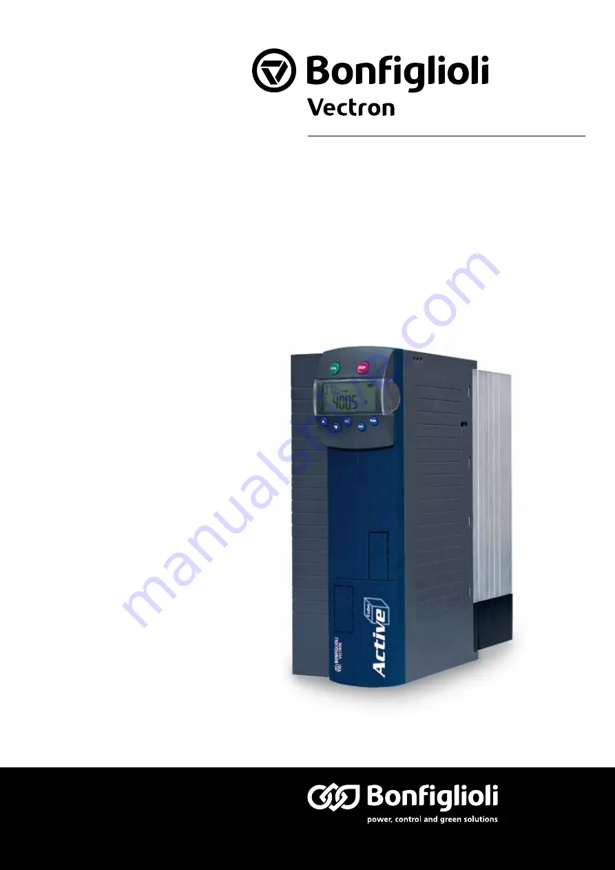
VEC 551 R1
ACTIVE CUBE
Application manual - Electronic gear
Position control and index control
Bonfiglioli has been designing and developing innovative
and reliable power transmission and control solutions
for industry, mobile machinery and renewable energy
applications since 1956.


