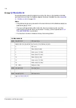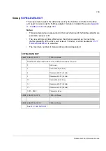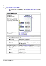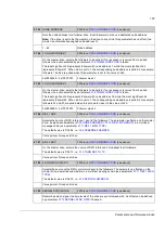
Parameters and firmware blocks
163
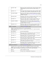
(5)
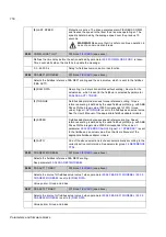
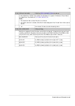
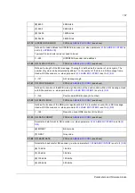
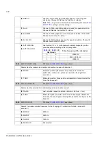
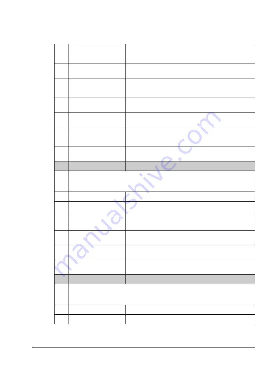
FEN-11 ABS
Module type: FEN-11 Absolute Encoder Interface. Emulation: FEN-11
absolute encoder input (X42) position is emulated to FEN-11 TTL
output.
(6)
FEN-11 TTL
Module type: FEN-11 Absolute Encoder Interface. Emulation: FEN-11
TTL encoder input (X41) position is emulated to FEN-11 TTL output.
(7)
FEN-21 SWREF
Module type: FEN-21 Resolver Interface. Emulation: Drive software
position (source selected by par.
) is emulated
to FEN-21 TTL output.
(8)
FEN-21 RES
Module type: FEN-21 Resolver Interface. Emulation: FEN-21 resolver
input (X52) position is emulated to FEN-11 TTL output.
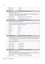
(9)
FEN-21 TTL
Module type: FEN-21 Resolver Interface. Emulation: FEN-21 TTL
encoder input (X51) position is emulated to FEN-21 TTL output.
(10)
FEN-31 SWREF
Module type: FEN-31 HTL Encoder Interface. Emulation: Drive
software position (source selected by par.
) is
emulated to FEN-31 TTL output.
(11)
FEN-31 HTL
Module type: FEN-31 HTL Encoder Interface. Emulation: FEN-31 HTL
encoder input (X82) position is emulated to FEN-31 TTL output.
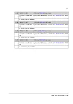
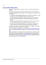
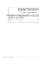
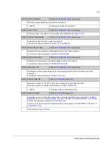
90.04
TTL ECHO SEL
(see above)
Enables and selects the interface for the TTL encoder signal echo.
Note:
If encoder emulation and echo are enabled for the same FEN-xx TTL output, the emulation
overrides the echo.
(0)
DISABLED
No echo interface enabled.
(1)
FEN-01 TTL+
Module type: FEN-01 TTL Encoder Interface. Echo: TTL encoder
input (X32) pulses are echoed to the TTL output.
(2)
FEN-01 TTL
Module type: FEN-01 TTL Encoder Interface. Echo: TTL encoder
input (X31) pulses are echoed to the TTL output.
(3)
FEN-11 TTL
Module type: FEN-11 Absolute Encoder Interface. Echo: TTL encoder
input (X41) pulses are echoed to the TTL output.
(4)
FEN-21 TTL
Module type: FEN-21 Resolver Interface. Echo: TTL encoder input
(X51) pulses are echoed to the TTL output.
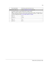
(5)
FEN-31 HTL
Module type: FEN-31 HTL Encoder Interface. Echo: HTL encoder
input (X82) pulses are echoed to the TTL output.
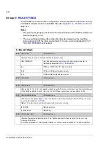
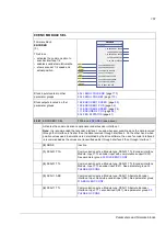
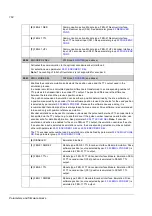
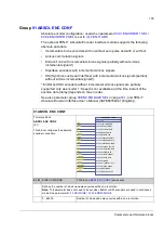
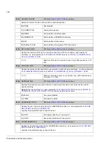
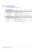
90.05
ENC CABLE FAULT
(see above)
Selects the action in case an encoder cable fault is detected by the FEN-xx encoder interface.
Note:
At the time of printing, this functionality is only available with the absolute encoder input of the
FEN-11 based on sine/cosine incremental signals, and with the HTL input of the FEN-31.
(0)
NO
Cable fault detection inactive.
(1)
FAULT
The drive trips on an ENCODER 1/2 CABLE fault.
Summary of Contents for ACSM1 Series
Page 1: ...ACSM1 Firmware Manual ACSM1 Speed and Torque Control Program...
Page 2: ......
Page 4: ......
Page 12: ...Table of contents 12...
Page 49: ...Drive control and features 49...
Page 282: ...Standard function blocks 282...
Page 306: ...Application program template 306...
Page 312: ...Control chain block diagrams 312...
Page 331: ...331...
Page 332: ...332...
Page 333: ......


