
Start-up
28
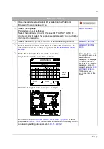
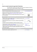
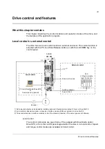
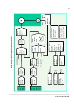
How to control the drive through the I/O interface
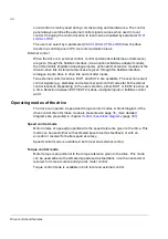
The table below instructs how to operate the drive through the digital and analogue
inputs, when the default parameter settings are valid.
PRELIMINARY SETTINGS
Ensure the original parameter settings (default) are valid.
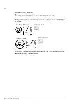
Ensure the control connections are wired according to the connection
diagram given in chapter
Default connections of the control unit
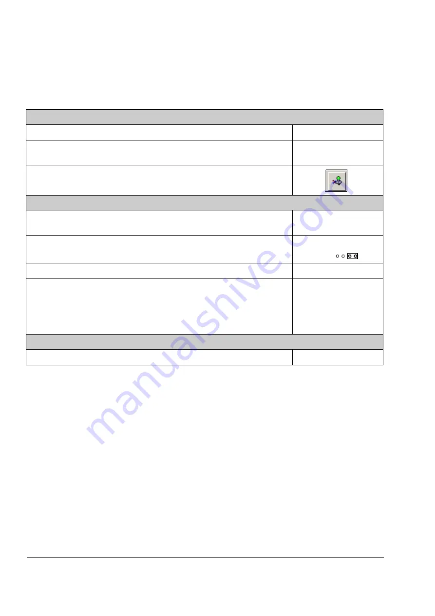
Switch to external control by clicking the Take/Release button of the PC
tool control panel.
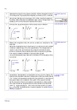
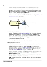
STARTING AND CONTROLLING THE SPEED OF THE MOTOR
Start the drive by switching digital input DI1 on. Digital input status can be
monitored with signal
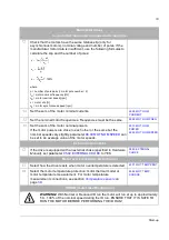
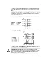
Check that analogue input AI1 is used as a voltage input (selected by
jumper J1).
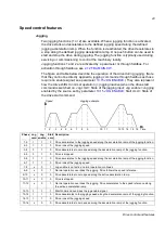
Regulate the speed by adjusting the voltage of analogue input AI1.
Check analogue input AI1 signal scaling. AI1 values can be monitored
with signals
and
When AI1 is used as a voltage input, the input is differential and the
negative value corresponds to the negative speed and the positive value
to the positive speed.
…
STOPPING THE MOTOR
Stop the drive by switching digital input DI1 off.
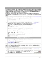
Voltage:
J1
Summary of Contents for ACSM1 Series
Page 1: ...ACSM1 Firmware Manual ACSM1 Speed and Torque Control Program...
Page 2: ......
Page 4: ......
Page 12: ...Table of contents 12...
Page 49: ...Drive control and features 49...
Page 282: ...Standard function blocks 282...
Page 306: ...Application program template 306...
Page 312: ...Control chain block diagrams 312...
Page 331: ...331...
Page 332: ...332...
Page 333: ......