background image


ENGEL Elektroantriebe GmbH · 

Am Klingenweg 10 · D-65396 Walluf


Telefon

 +49 6123 9942-0 · 

Telefax

 +49 6123 9942-50 · [email protected] · www.engelantriebe.de 


Operating Manual 


Rev. 1.3 


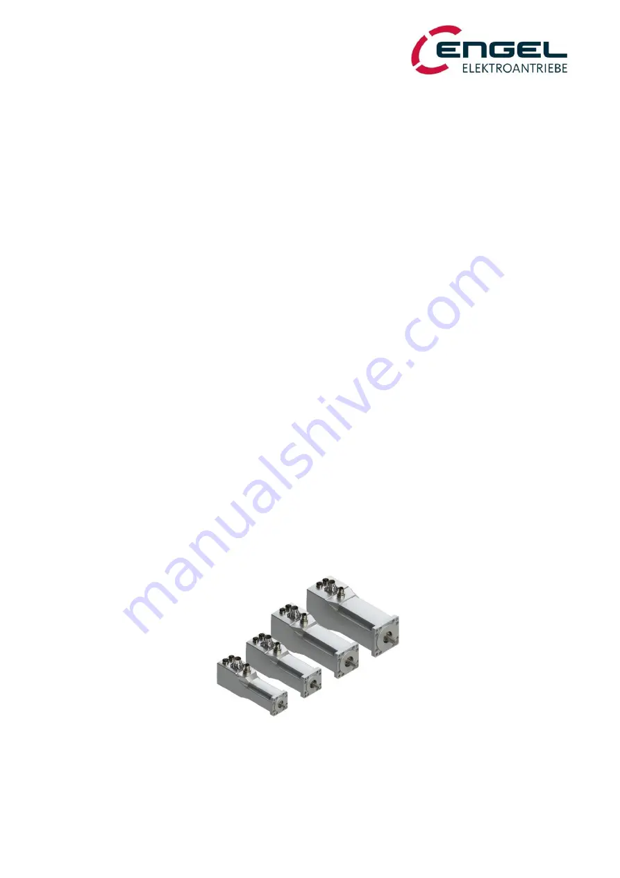
Integrated Synchronous Servo Drives


HFI22xx / HFI26xx 
HFI32xx / HFI37xx 


Summary of Contents for HFI 2230

Page 1: ...e GmbH Am Klingenweg 10 D 65396 Walluf Telefon 49 6123 9942 0 Telefax 49 6123 9942 50 info engelantriebe de www engelantriebe de Operating Manual Rev 1 3 Integrated Synchronous Servo Drives HFI22xx HFI26xx HFI32xx HFI37xx ...

Page 2: ... 8 5 Copyright The information and specifications in this document have been compiled with great care and to the best of our knowledge However specifications differing between the document and the product cannot be eliminated with absolute certainty ENGEL assumes no liability whatsoever for errors or consequential damages resulting from these deviations No liability is assumed for damages which ar...

Page 3: ...6 5 1 HFI3760 characteristics 16 6 5 2 HFI3790 characteristics 16 6 6 Important technical Information 17 6 6 1 Regenerative operation 17 6 6 2 Lead fuses 17 6 6 3 Service life expectancy 17 6 6 4 Safety installations 18 7 DSERV SERVICE SOFTWARE 19 7 1 System requirements 19 7 2 Installation and start up of the program 19 7 2 1 Installation of the software 19 7 2 2 Program start 20 7 2 2 1 Error me...

Page 4: ...e connection to X1 75 10 1 2 Requirements on the CAN line connection to X2 75 10 1 3 Requirements on the STO line connection to X3 77 10 1 4 Requirements on the fieldbus lines connection to X4 and X5 77 10 2 Installation diagram 78 11 COMMISSIONING 79 12 STATUS DISPLAY ERROR MESSAGES 80 12 1 Status display 81 12 1 1 HFI without communication module 81 12 1 2 HFI with communication module 81 12 1 2...

Page 5: ...are described in the corresponding documents CANopen Manual EtherCAT Manual 2 Symbols used in this document Symbol Signal Word Meaning Attention This symbol refers to safety and warning notices Non observance can result in personal injury and or damage to property Note This symbol refers to useful hints which should help to avoid or find errors 3 Abbreviations used in this document Abbreviation Me...

Page 6: ...sured that the drive does not pose any hazards and that no uncontrolled movements can occur Do not plug or unplug connectors while energized The following regulations apply with no claim to completeness VDE 0100 Low voltage electrical installations EN 60204 1 Safety of machinery Electrical equipment of machines EN 61800 Adjustable speed electrical power drive systems Attention Functional Safety Fo...

Page 7: ... 40 series Furthermore the device is available in a CAN variant In this variant no communication module is required Communica tion takes place via CANopen according to CiA DSP 402 V2 0 The simple parameterisation configuration of the device takes place with the parameterisation software DSerV WIN DOWS COM Port Overview of features dynamic compact drives for decentralised use no space in the contro...

Page 8: ...290 3760 3790 Series HFI List of options non exhaustive HB parking brake permanent magnetic installed in the motor CO CANopen Interface additional M12 connector EC EtherCAT fieldbus communication module EI EtherNet IP fieldbus communication module PN PROFINET fieldbus communication module SC surface coating housing GPK xxx planetary gear GPK mounted onto the motor gear reduction xxx 1 Attention Fu...

Page 9: ...Uon 30 DI1 control enable DI4 DI5 can optionally be used as digital output DO2 DO1 Digital Outputs DO1 DO2 24 V 50 mA open collector ground switch ing 3 33 series resistance without pull up resistor can optionally be used as inputs Serial Interfaces RS232 Communication with DSerV parameterisation software CAN 2 0B max 1 MBit s galvanically isolated without termination resistor Electromagnetic comp...

Page 10: ...t is the direct current drawn in nominal operation rated torque at rated speed from the input voltage 24 VDC or 48 VDC The current drawn from the input voltage is proportional to the converted power not to be confused with the torque building motor current which is displayed as sine peak value in DSerV and is pro portional to the motor torque Please also observe that the supply line is lossy This ...

Page 11: ...7xx System Data HFI22xx HFI2230 characteristics Operating Manual Rev 1 3 www engelantriebe de Page 10 6 2 1 HFI2230 characteristics Figure 6 1 HFI2230 characteristics 24 V 4000 5000 rpm 6 2 2 HFI2260 characteristics Figure 6 2 HFI2260 characteristics 24 V 3000 4000 rpm ...

Page 12: ...rect current drawn in nominal operation rated torque at rated speed from the input voltage 24 VDC or 48 VDC The current drawn from the input voltage is proportional to the converted power not to be confused with the torque building motor current which is displayed as sine peak value in DSerV and is propor tional to the motor torque Please also observe that the supply line is lossy This leads to a ...

Page 13: ...7xx System Data HFI26xx HFI2630 characteristics Operating Manual Rev 1 3 www engelantriebe de Page 12 6 3 1 HFI2630 characteristics Figure 6 3 HFI2630 characteristics 24 V 4000 5000 rpm 6 3 2 HFI2660 characteristics Figure 6 4 HFI2660 characteristics 24 V 3000 4000 rpm ...

Page 14: ...ct current drawn in nominal operation rated torque at rated speed from the input voltage 24 VDC or 48 VDC The current drawn from the input voltage is proportional to the converted power not to be confused with the torque building motor current which is displayed as sine peak value in DSerV and is pro portional to the motor torque Please also observe that the supply line is lossy This leads to a re...

Page 15: ...7xx System Data HFI32xx HFI3260 characteristics Operating Manual Rev 1 3 www engelantriebe de Page 14 6 4 1 HFI3260 characteristics Figure 6 5 HFI3260 characteristics 48 V 3000 4000 rpm 6 4 2 HFI3290 characteristics Figure 6 6 HFI3290 characteristics 48 V 3000 4000 rpm ...

Page 16: ...eration rated torque at rated speed from the input voltage 24 VDC or 48 VDC The current drawn from the input voltage is proportional to the converted power not to be confused with the torque building motor current which is displayed as sine peak value in DSerV and is propor tional to the motor torque Please also observe that the supply line is lossy This leads to a reduction in voltage and speed a...

Page 17: ...7xx System Data HFI37xx HFI3760 characteristics Operating Manual Rev 1 3 www engelantriebe de Page 16 6 5 1 HFI3760 characteristics Figure 6 7 HFI3760 characteristics 48 V 3000 4000 rpm 6 5 2 HFI3790 characteristics Figure 6 8 HFI3790 characteristics 48 V 3000 4000 rpm ...

Page 18: ...for the decoupling of the operating voltage The effect of the voltage increase when braking can be reduced if necessary by selecting a less abrupt that is a longer deceleration ramp If applicable regenerated energy can be distributed to other loads connected to the supply voltage in parallel If regenerated braking energy cannot be converted the terminal voltage rises until an overvoltage error Err...

Page 19: ...implemented The overcurrent short circuit monitor detects excessive current flow in the motor phases The I t monitor protects the motor and power stage from thermal overload by limiting the motor current to the rated current see chapter 8 2 1 4 Parameters of the current control loop after the lapse of a permissible overload duration The overload duration depends on various factors For a detailed d...

Page 20: ...e see chapter 10 2 Installation diagram 7 2 Installation and start up of the program Note Read the licence agreement on the provided data carrier of the software before installation With the installation of the DSerV service software you agree to the conditions of the li cense agreement 7 2 1 Installation of the software For the installation of DSerV it is sufficient to copy the program files to a...

Page 21: ...possible After the start up of the service software the DSerV program window appears and the communication to the connected device is automatically established 7 2 2 1 Error messages after program start If the error message DAV file not found appears please check if a dav file in the working directory corresponds to the type of device and firmware used If necessary contact the ENGEL customer suppo...

Page 22: ...not use any of the following characters in Name 4 Click OK to close the Properties window 5 Double click the shortcut to start the new DSerV instance When a DSerV instance is started an initialisation file Name ini e g Drive_1 ini will be created that holds all program settings like the COM port to be used for the specific instance Remember that at first start up of this instance DSerV may not aut...

Page 23: ...tatus etc Fieldbus status bar Network status state machine Node ID bit rate Drive status bar Device type firmware serial number enable error messages When you click on one of the Drive status fields lettered in blue the device information and the overall operating hours will be displayed The overall operating hours comprise the hours of operation supply voltage applied and the enable hours power s...

Page 24: ...ion Download transfers the selected parameter file to the device A list view presents an overview of the existing parameter files along with their descriptions and additional in formation To transfer a parameter file to the drive select an entry from the list then click the Download but ton The new parameters will be stored permanently in the drive replacing all previous parameters The circle in f...

Page 25: ... de Page 24 Firmware Download Opens the dialogue for the firmware update of the device Follow the instructions on the screen During the update DSerV transmits a new software to the device via the existing connection Firm ware files hex are available on request please contact the ENGEL customer support Close Closes DSerV Figure 7 9 Firmware Download dialogue ...

Page 26: ...u for a detailed description see chapter 8 Parameterisation Operating mode Selection between current control speed control and positioning mode Selection of set point source Fieldbus operation Activation of fieldbus mode address setting bit rate setting Current controller Adjustment of current limits and parameters of the current controller Specification of the motor pole number and angle sensor o...

Page 27: ...ntriebe de Page 26 7 3 3 Monitor menu In the Monitor menu a set of runtime values and status information can be selected or deselected individually for dis play Note With an increasing number of open monitor windows the refresh rate of the individual val ues may decrease Close unneeded windows Figure 7 11 Monitor menu Figure 7 12 View of monitor values ...

Page 28: ...DC Link Voltage Power Stage Input Current Power Stage Input Power Motor Temperature For integrated drives motor temperature power stage temperature Power Stage Temperature Temperature of the power stage I t Monitor Shows the overcurrent capability of the device Rising values Overcurrent condition When reaching 100 the motor current is automatically reduced to motor rated current When falling below...

Page 29: ...ontents can be displayed individually in binary decimal or hexadecimal system To change the numeral system right click on the appropriate value field and choose the desired numeral system Objects with write access can be changed via the CAN editor which opens when you double click the object s value field A new value is transmitted to the drive by clicking the green arrow or by hitting the enter b...

Page 30: ...is generated that indicates when the memory was last deleted 7 3 5 Options menu In the Options menu the COM port to be used can be selected It may take a few seconds until all COM ports COM1 COM99 are scanned and the ones that were found are displayed When a COM port is selected DSerV imme diately tries to establish a connection to the device via this port 7 3 6 menu ENGEL Homepage Link to the ENG...

Page 31: ...ntrol interface The description of the device functions in this document assumes operation without fieldbus I O mode In fieldbus mode the same functionality is basically available and is described in detail in the corresponding fieldbus manuals For reference the relevant fieldbus objects signals are also listed in this document Notes for fieldbus operation All parameters can be changed via the cor...

Page 32: ...peed control speed control without current limitation speed control with current limitation Positioning homing linear positioning mode turntable positioning mode The operating modes can be selected as follows depending on the control interface type Control I F Menu Object Telegram I O mode Optimisation Operating mode CANopen Modes of Operation 6060h EtherCAT Modes of Operation 6060h EtherNet IP Mo...

Page 33: ... motor in Nm A as stated in the data sheet 8 2 1 1 Current control with without speed limitation Current control can be carried out with or without speed limitation Current control with speed limitation can be used for example to limit a current controlled drive to a defined speed when there is no load Without limitation the drive would accelerate to its maximum possible speed Current control with...

Page 34: ...rating mode Current control Speed limit CANopen Modes of Operation 6060h 4 EtherCAT Modes of Operation 6060h 4 EtherNet IP Modes of Operation 6060h 4 PROFINET ENGEL Telegram 100 Modes of Operation 6060h 4 not available via standard telegrams Note For the proper function of the current control mode with speed limitation the param eters of the speed controller must also be set The acceleration and d...

Page 35: ... in 0 1 steps by left clicking in the free space of the slider component Constant values Two fixed setpoints can be defined via constant value 1 2 Digital input DI6 switches be tween the constant values 1 2 see chapter 8 3 Digital inputs limit switches The setpoint values are defined as a percentage of the motor rated current adjustable via Op timisation Current controller Motor rated current i e ...

Page 36: ...coarse adjustment of the limit value is possible with the slider The limit value can be changed in 10 steps using the arrow keys and in 0 1 steps by left clicking in the free space of the slider component The limit values are defined as a percentage of the Setpoint Scaling adjustable via Optimisa tion Speed Controller Setpoint Scaling i e 100 Setpoint Scaling value see chapter 8 2 2 4 Parameters o...

Page 37: ...ode Setup via DSerV CANopen Max Current 6073h EtherCAT Max Current 6073h EtherNet IP Max Current 6073h PROFINET Max Current 6073h not available via telegrams must be directly addressed Motor rated current The current that the motor and electronics can carry permanently without thermal over load With I O control a current setpoint of 100 corresponds to motor rated current With fieldbus control curr...

Page 38: ...f the PI type current control loop tn_i 0 1 3 276 7 ms Control I F Menu Object Telegram I O mode Setup via DSerV CANopen Torque Control Parameters 60F6h sub2 tn_i EtherCAT Torque Control Parameters 60F6h sub2 tn_i EtherNet IP Torque Control Parameters 60F6h sub2 tn_i PROFINET Torque Control Parameters 60F6h sub2 tn_i not available via telegrams must be directly addressed Number of poles Number of ...

Page 39: ...d drive to a defined torque i e current In this way it can be prevented for example that unin tentionally high forces are generated at the output if the motor is blocked Speed control without torque limitation can be selected as follows depending on the control interface type Control I F Menu Object Telegram I O mode Optimisation Operating Mode Speed Control CANopen Modes of Operation 6060h 3 Ethe...

Page 40: ... limit CANopen Modes of Operation 6060h 3 EtherCAT Modes of Operation 6060h 3 EtherNet IP Modes of Operation 6060h 3 PROFINET ENGEL Telegram 100 Modes of Operation 6060h 3 not available via standard telegrams Notes Prior to setting up or operating the speed controller make sure that the current limits and the parameters of the current controller are set correctly see chapter 8 2 1 4 Parameters of ...

Page 41: ...eps using the arrow keys and in 0 1 steps by left clicking in the free space of the slider component Constant values Two fixed setpoints can be defined via constant value 1 2 Digital input DI6 switches be tween the constant values 1 2 see chapter 8 3 Digital inputs limit switches The setpoint values are defined as a percentage of the setpoint scaling adjustable via Optimi sation Speed Controller S...

Page 42: ...ation is internally achieved by limiting the torque producing current Thus the limit values are defined as a percentage of the motor peak current Optimisation Current con troller Motor peak current i e 100 motor peak current see chapter 8 2 1 4 Parameters of the current control loop The limit values are evaluated by amount i e a negative limit value has the same effect as a positive limit value Th...

Page 43: ... Setpoint Scaling With I O control a speed setpoint of 100 corresponds to the Setpoint Scaling value Example with AI1 as setpoint source AE1 2 V Setpoint scaling 3000 RPM Speed setpoint 2 V 10 V 3000 RPM 600 RPM With fieldbus control the speed setpoint is not normalized to a maximum speed see corresponding fieldbus manual Setpoint ramp With this menu item the ramp characteristic of the speed setpo...

Page 44: ...Profile Type 6086h 0 Profile Acceleration 6083h Profile Deceleration 6084h EtherCAT Motion Profile Type 6086h 0 Profile Acceleration 6083h Profile Deceleration 6084h EtherNet IP Motion Profile Type 6086h 0 Profile Acceleration 6083h Profile Deceleration 6084h PROFINET Motion Profile Type 6086h 0 MDI_ACC or ENGEL Telegram 100 Profile Acceleration 6083h MDI_DEC or ENGEL Telegram 100 Profile Decelera...

Page 45: ...h PROFINET Motion Profile Type 6086h 1 MDI_ACC or ENGEL Telegram 100 Profile Acceleration 6083h MDI_DEC or ENGEL Telegram 100 Profile Deceleration 6084h not available via standard telegram 1 Notes With I O control the SIN ramp is not available in speed control mode With fieldbus control the SIN ramp is available in speed control mode With I O control DSerV allows a time interval each to be entered...

Page 46: ... Motion Profile Type 6086h 1 PROFINET Motion Profile Type 6086h 1 not available via telegrams must be directly addressed Notes In some applications the deactivation of the ramps may be necessary e g if the speed ramps are provided by an external source e g a PLC and further delays are not desired If not explicitly requested the ramps should normally not be switched off The positioning mode require...

Page 47: ...e via telegrams must be directly addressed Time constant Integral time of the PI type speed control loop tn_n 0 1 3 276 7 ms For optimal setting of tn_n see chapter 13 3 Speed controller adjustment Control I F Menu Object Telegram I O mode Setup via DSerV CANopen Velocity Control Parameter Set 60F9h sub2 tn_n EtherCAT Velocity Control Parameter Set 60F9h sub2 tn_n EtherNet IP Velocity Control Para...

Page 48: ...gram I O mode Optimisation Operating mode Positioning Turntable CANopen Modes of Operation 6060h 5 EtherCAT Modes of Operation 6060h 5 EtherNet IP Modes of Operation 6060h 5 PROFINET ENGEL Telegram 100 Modes of Operation 6060h 5 not available via standard telegrams Homing A reference run serves for the detection of a defined machine position It is normally mandatory with the use of angle sensors w...

Page 49: ...de the homing starts automatically whereby it is possible to choose whether the homing should only be carried out the first time the drive is enabled after power on or every time the drive is enabled After successful referencing the drive automatically switches to positioning mode CANopen Modes of Operation 6060h 6 EtherCAT Modes of Operation 6060h 6 EtherNet IP Modes of Operation 6060h 6 PROFINET...

Page 50: ... a ccw direction of ro tation Note that the direction of rotation is unaffected by the polarity parameter see chapter 8 2 3 2 General positioning parameters If the switch is already active or if it gets activated the drive reverses and moves down from the switch with a low Speed during search for zero The position at which the switch goes inactive is interpreted as home position and the movement s...

Page 51: ...n negative limit switch index pulse CANopen positive Homing Method 6098h 2 negative Homing Method 6098h 1 EtherCAT positive Homing Method 6098h 2 negative Homing Method 6098h 1 EtherNet IP positive Homing Method 6098h 2 negative Homing Method 6098h 1 PROFINET positive Standard Telegram 9 SATZANW 1xxx xxxx 0000 0010 negative Standard Telegram 9 SATZANW 1xxx xxxx 0000 0001 not available via ENGEL te...

Page 52: ...ical stop the motor current is switched off Control I F Menu Object Telegram I O mode positive On positive mechanical stop negative On negative mechanical stop CANopen positive Homing Method 6098h 18 negative Homing Method 6098h 17 EtherCAT positive Homing Method 6098h 18 negative Homing Method 6098h 17 EtherNet IP positive Homing Method 6098h 18 negative Homing Method 6098h 17 PROFINET positive S...

Page 53: ... 1 transition or ENGEL Telegram 100 Controlword 6040h Bit 4 0 to 1 transition Speeds This menu item is used to parameterise the speed profile to be used for the reference run Acceleration Specifies the ramp slope unit 10 RPM s or the ramp time unit ms of the speed ramp de pending on whether a linear ramp or a SIN ramp is selected This value applies to all speed changes throughout the reference run...

Page 54: ...h for zero EtherNet IP Homing Speeds 6099h sub2 speed during search for zero PROFINET Standard Telegram 9 MDI_VELOCITY not available ENGEL telegram 100 Offset Offset between the home position determined in the reference run and the zero position of the machine Figure 8 29 Home offset Control I F Menu Object Telegram I O mode Setup via DSerV CANopen Home Offset 607Ch EtherCAT Home Offset 607Ch Ethe...

Page 55: ...ly attempts to minimise the difference between the demanded position and the actual position value For this purpose it increases or decreases the demanded speed whose maximum permissible deviation from the pre calculated trajectory speed is specified by the Correction speed parameter Example With a travel speed of 3000 rpm and a Correction speed of 300 rpm the position controller can adjust the de...

Page 56: ...osition Control Parameter Set 60F9h sub2 vkorrigier PROFINET Position Control Parameter Set 60F9h sub2 vkorrigier not available via telegrams must be directly addressed Polarity This parameter allows the internal reversal of the positioning direction for adaptation to the mechani cal conditions of the application Polarity positive increasing position values with motor shaft rotating cw Polarity ne...

Page 57: ... Limit 607Dh sub2 Max Position Limit PROFINET Software Position Limit 607Dh sub2 Max Position Limit not available via telegrams must be directly addressed Turntable positioning range Position where the position counter overflows and is reset to zero when in turntable positioning mode Control I F Menu Object Telegram I O mode Setup via DSerV CANopen Position Range Limit 607Bh sub2 Max Position Rang...

Page 58: ...FINET Standard Telegram 9 ZSW1 Bit10 or ENGEL Telegram 100 Statusword 6041h Bit 10 Position window The value parameterised under Position window defines a tolerance range around the tar get position The actual position must be within this range for a defined period of time Position window time before the positioning process is considered completed Figure 8 35 Position window Control I F Menu Objec...

Page 59: ...tion Window Time 6068h EtherCAT Position Window Time 6068h EtherNet IP Position Window Time 6068h PROFINET Position Window Time 6068h not available via telegrams must be directly addressed Note The target reached condition is only evaluated after the positioning process has reached the braking phase and before a subsequent positioning process is initiated see Figure 8 17 Positioning procedure Figu...

Page 60: ... define the size of the window PROFINET Following Error Window 6065h The following error monitoring is active if Bit 31 0 Bits 0 30 define the size of the window not available via telegrams must be directly addressed Following error timeout The value parameterised under Following error timeout defines how long the abso lute value of the difference between actual position and setpoint position is a...

Page 61: ... EtherCAT Signalisation in object Statusword 6041h Bit13 and triggering of a positioning error that leads to the power stage being switched off EtherNet IP Signalisation in object Statusword 6041h Bit13 and triggering of a positioning error that leads to the power stage being switched off PROFINET Standard Telegram 9 no signalisation in STW1 ENGEL Telegram 100 Signalisation in object Statusword 60...

Page 62: ...bering of the target IDs starts at 0 Example DI8 DI7 DI6 1 1 0 bin 6 dec Target ID 6 Target position The target position is the end position to be approached by the positioning control Control I F Menu Object Telegram I O mode Setup via DSerV CANopen Target Position 607Ah EtherCAT Target Position 607Ah EtherNet IP Target Position 607Ah PROFINET Standard Telegram 9 MDI_TARPOS or ENGEL Telegram 100 ...

Page 63: ... is determined solely by the sign of the target position Positive target positions will be approached in cw rotation negative target posi tions in ccw rotation The shortest path option is not available in this case Starting condition It can be selected whether a new positioning process is only started after a still active positioning process is completed or whether a still active positioning proce...

Page 64: ...040h Bit 6 0 AND Bit11 1 EtherCAT Controlword 6040h Bit 6 0 AND Bit11 1 EtherNet IP Controlword 6040h Bit 6 0 AND Bit11 1 PROFINET Standard Telegram 9 MDI_MOD Bit1 AND Bit2 0 or ENGEL Telegram 100 Controlword 6040h Bit 6 0 AND Bit 11 1 Turntable direction If the Target position is specified as an absolute value with a defined direction of rotation the direction of rotation can be specified here cw...

Page 65: ...able positioning Permissible value range for Target position in turntable positioning mode a with absolute positioning 0 0000 R Turntable positioning range If an absolute positioning process is started whereby the new target position is iden tical to the current setpoint position no positioning movement will be initiated b with relative positioning Turntable positioning range Turntable positioning...

Page 66: ...hey are not queued Instead only the last positioning command issued will prevail and will be executed as soon as the current positioning operation is finished This must be taken into account for the timing of the posi tioning jobs Example Figure 8 41 shows a positioning job 1 Target 1 200 R followed quickly by positioning job 2 Target 2 300 R and positioning job 3 Target 3 150 R Positioning job 1 ...

Page 67: ...tion of the movement range of the drive and can also be used as reference switches to determine the home position see chapter 8 2 3 1 Homing If no limit switches are to be used parameterize the selection shown in Figure 8 42 which also corresponds to the facto ry default The limit switch parameterisation can only be changed via DSerV Limit switch monitoring Inactive Function varies depending on op...

Page 68: ...in order to prevent torques in the nega tive direction Positive setpoints are not influenced 4 An actuated limit switch does not trigger a positioning error 5 An actuated limit switch triggers a positioning error 6 Digital input DI2 can be assigned one of two possible functions Setpoint 0 or HALT Currently this setting is not user selectable and can only be preset at the factory Default setting Se...

Page 69: ...oint Start positioning A rising edge starts the next positioning process either immediately or after the completion of a still active positioning process depending on the parameterisation see chapter 8 2 3 3 Target positions Target ID Bit 0 2 Selection of a target record ID 0 7 binary coded which will be activated with the next start of a positioning process A target record mainly comprises a targ...

Page 70: ...digital output is only available if the corresponding digital input is not required The following DO availability arises depending on the operating mode Current control Speed control Positioning I O mode DO1 DO2 DO1 DO2 DO1 DO2 Fieldbus mode DO1 DO2 DO1 DO2 DO1 DO2 See also the tabular overview in chapter 8 3Digital inputs limit switches In fieldbus mode both DOs are always available as DI4 is not...

Page 71: ...an error state Pos logic A function as described above is assigned to the DO Neg logic A function as described above is inverted before it is assigned to the DO The Ready function for example becomes a Not Ready function if negative logic is selected In this example the function is TRUE if the drive is in an error state and FALSE if the drive is error free Threshold If one of the threshold functio...

Page 72: ... overload duration of approx 5 s at an overload of Iactual 2 Irated As soon as the sum falls below 50 of the threshold value again it is possible to operate in overcurrent mode again taking into account that the sum is not yet zero at this point This means that the maximum overload duration is consid erably reduced if the overcurrent operation is repeated while the sum is not yet at zero The I t f...

Page 73: ...0 Halt positive limit switch L 0 5 V H 15 30 V 3 GN DI3 Digital input 3 setpoint inverse negative limit switch L 0 5 V H 15 30 V 4 YE DO1 Digital output 1 configurable function Open Coll 24 V 50 mA DI5 Digital input 5 currently not usable as DI L 0 5 V H 15 30 V 5 GY DO2 Digital output 2 configurable function Open Coll 24 V 50 mA DI4 Digital input 4 start positioning process 4 L 0 5 V H 15 30 V 6 ...

Page 74: ... Shield 2 CAN Shield 2 RD 2 x 1 04 mm 2 n c 3 BK CAN_GND CAN reference potential 4 WH 2 x 0 52 mm 2 CAN_H CAN High signal 5 BU CAN_L CAN Low signal 1 Wire colours and cross sections apply for ENGEL standard connection cables 2 If a shielded cable is used the shield connection should preferably be made via the connector housing In addition the shield can also be contacted via Pin 1 The CAN interfac...

Page 75: ...1 positive potential 24V 5 n c 6 STO2 supply STO channel 2 positive potential 24V 7 STO2 supply STO channel 2 reference potential 0V 8 n c 9 4 X4 X5 Fieldbus modules Connector on the device 4 pin M12 circular connector female D coded Mating plug 4 pin M12 circular connector male D coded Pin No Wire1 Name Description 1 YE 2 x 2 x 0 34 mm TX Transmit Data 2 WH RX Receive Data 3 OG TX Transmit Data 4...

Page 76: ... and have shielding Minimum wire cross section for signals 0 14 mm Flexibility and temperature range in accordance with the specific application Connect the overall shield with the lowest possible impedance to functional earth Type recommendation ENGEL original accessories Item No 9900000575 2 m Item No 9900000576 5 m Cable assembly with connection plug open on one end 3 x 1 5 mm shielded 12 x 0 1...

Page 77: ... female 5 pin 1 1 M12 e g Lapp Kabel Item no 22260765 CANopen Bus cable 1x male 1x female 5 pin M12 e g Lapp Kabel Item no 22260795 22260799 CANopen Terminating resistor M12 e g Lapp Kabel Item no 22260766 Figure 10 1 CAN network with Y connector Figure 10 2 CAN network with T connector Note With the use of a T connector rotating receptacles for the drives can no longer be com pletely turned towar...

Page 78: ...accessories Item No 9900000650 5 m Item No 9900000651 15 m Cable assembly with M12 connection plug open on one end 8x 0 25mm shielding applied on sleeve nut 10 1 4 Requirements on the fieldbus lines connection to X4 and X5 Cat 5e or higher category cable Overall shield Flexibility and temperature range in accordance with the specific application Type recommendation ENGEL original accessories Item ...

Page 79: ...ading to a controller e g R1 1 k 1 W to 24 VDC Separate logic supply To maintain the data on shut down or failure of the main supply Ub 24 VDC 48 VDC it is possible to feed a separate logic supply voltage Ubl 24 VDC 48 VDC to X1 The reference potential of each of the two voltage supplies is to be connected to X1 Pin B 0 V Analogue Input For correct functionality of the differential analogue input ...

Page 80: ...the DSerV service software Connect COMx x 1 99 of your PC laptop and connector X1 of the drive according to chapter 10 2Installation diagram then start the DSerV service software The status bar of the program will show the type and version of the connected device see chapter 7 3 Using the DSerV service software Remedy for faulty communication See chapter 7 2 Installation and start up of the progra...

Page 81: ...g cause of error an error message can be reset by switching the enable input DI1 OFF ON The power stage and the controller are only activated after switching the enable input OFF ON a second time only applies to I O mode for fieldbus mode see CANopen user manual t1 Occurrence of an error Power stage disabled immediately error message active t2 Error cause is rectified t3 Enable input set to inacti...

Page 82: ...us LED LED green LED red Operating status blinking OFF Drive ready controller power stage disabled ON OFF Drive ready controller power stage enabled OFF blinking Error status Red LED indicates the highest active error code OFF OFF Device has no function Check input voltage Firmware download mode active red LED glows weakly RESET active e g on start up Figure 12 2 HFI without communication module r...

Page 83: ...linking Recoverable fault s Module is configured but stored parameters differ from cur rently used parameters Note A test sequence is performed on these LEDs during start up 12 1 2 2 EtherCAT LED1 RUN LED LED green LED red Operating Status OFF OFF Module in INIT state or no power ON OFF Module in OPERATIONAL state blinking OFF Module in PRE OPERATIONAL state 1 flash OFF Module in SAFE OPERATIONAL ...

Page 84: ...ls to identify the node on the network OFF ON Major internal error this indication is combined with a red module status LED OFF 1 flash Station Name not set OFF 2 flashes IP address not set OFF 3 flashes Expected Identification differs from Real Identification LED2 Module Status LED green LED red Operating State OFF OFF No power Module in SETUP or NW_INIT state ON OFF Normal Operation module has s...

Page 85: ...meters of the current controller are adjusted according to the factory settings 8 Parameter memory checksum error The contents of the parameter memory were read incorrectly If the error occurs again after a power on reset then Download a well proven parameter set or Check all parameter settings in the DSerV Optimisation menu then save them with the Save settings menu 9 Faulty parameter set The par...

Page 86: ... 5 Faulty parameterisation of the posi tioning range Illegal parameterisation of the positioning range limits min max 6 Limit switch monitoring At least one of the two limit switches which limit the position ing range was unexpectedly activated 7 Homing With fieldbus control Incorrectly parameterised unknown homing method When referencing to a limit switch The opposite limit switch was actuated du...

Page 87: ...he DSerV service software 12 5 CAN error messages Displayed error no Meaning Cause Measures for error rectification 1 CAN Controller overflow Bus load too high cannot be processed Reduce the CAN bit rate if applicable Optimise the PDO communication 2 CAN bus off Communication switched off due to disrupted transmission Check that the correct baud rate has been set Check that the Node ID is correct ...

Page 88: ...ondition as supplied load the originally supplied parameter set into the device 13 2 Angle sensor offset determination motor pole number The parameters for the motor pole number see chapter 6 1 System Data and angle sensor offset are factory preset and should not normally be changed In the DSerV menu Optimisation Current controller see chapter 8 2 1 4 Parameters of the current control loop the par...

Page 89: ...peed control loop To optimise the speed controller the setpoint ramp must be switched off Ramps inactive or set to maximum acceleration The setpoint scaling value must be set according to the speed required in the application The control parameters of the speed controller must initially be set to non critical values i e low pro portional gain kp_n 0 0500 0 1000 and a large time constant Step 5 The...

Page 90: ...s 14 1 HFI 2230 HFI 2260 Motor Type Dimension L1 without module Dimension L1 with module Dimension L2 HFI2230 129 143 8 HFI2230 with parking brake 161 175 10 HFI2260 159 173 8 HFI2260 with parking brake 191 205 10 14 2 HFI 2630 HFI 2660 Motor Type Dimension L without module Dimension L with module HFI2630 136 150 HFI2630 with parking brake 166 180 HFI2660 166 180 HFI2660 with parking brake 196 210...

Page 91: ...Dimension L without module Dimension L with module HFI3260 163 177 HFI3260 with parking brake 193 207 HFI3290 193 207 HFI3290 with parking brake 223 237 14 4 HFI 3760 HFI 3790 Motor Type Dimension L without module Dimension L with module HFI3760 168 182 HFI3760 with parking brake 198 212 HFI3790 198 212 HFI3790 with parking brake 228 242 Figure 14 3 HFI32xx dimensions Figure 14 4 HFI37xx dimension...

Page 92: ... motor mounting preferred in vertical position Flange must be flush with the gearbox tighten screws with torque TA K fit plastic covers TA K TA K Chart tightening torque clamping unit TA K gearbox size Ø motor shaft Screws 8 8 Width across flat Tightening torque Nm GPK45 8 M4 3 4 5 GPK55 9 M4 3 4 5 GPK65 11 M4 3 4 5 GPK75 14 M5 4 9 5 Tighten screws crosswise Screws must be secured Insert plastic c...

Reviews: