Danaher Motion DBL Series, Manual
The Danaher Motion DBL Series offers high-quality, precision motion control for a wide range of applications. Get the most out of your equipment by downloading the free user manual from manualshive.com. Ensure optimal performance with detailed instructions and troubleshooting tips right at your fingertips.
Share
Download


Reviews:
No comments
Related manuals for DBL Series

SF-50
Brand: HPI Racing Pages: 2

IRONHORSE GSD4 Series
Brand: AutomationDirect Pages: 32

P5-B01
Brand: Becker Pages: 20

E25
Brand: Becker Pages: 20

E22
Brand: Becker Pages: 28

11PS
Brand: Becker Pages: 52

MG A C Series
Brand: UNI Geräte Pages: 14
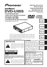
dvd-u05s
Brand: Pioneer Pages: 80

3MR8
Brand: ICAN Pages: 14

V160K
Brand: Pro-dig Pages: 26

24DC100A
Brand: Knightsbridge Pages: 4

SS2 Series
Brand: Shihlin Pages: 4

SubDrive Connect Plus SDCP-SUB1023
Brand: Franklin Electric Pages: 12

MD-90
Brand: Minolta Pages: 26

COMBIVERT F4-F
Brand: KEB Pages: 300

Allen-Bradley PowerFlex 520 Series
Brand: Rockwell Automation Pages: 272

B550-2001
Brand: Bedford Pages: 116

PD45
Brand: Stanley Pages: 20


