


Manual 26641
2301E Digital Control
Woodward
89
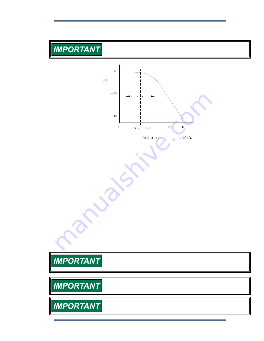
As the filter frequency is reduced, steady state stability improves but transient
performance may worsen. As the filter frequency is increased, steady state
stability worsens but transient performance may improve.
If the calculated firing frequency is greater that 15.9 Hz, then disable
the filter by setting the filter cutoff frequency at or above 15.9 Hz.
Figure 4-4. Speed Filter
10 BUMP ACT TRIGGER (T THEN F)
dflt = FALSE (FALSE, TRUE)
Allows you to test your dynamics settings by temporarily applying a decreased
fuel demand transient to stimulate a control response. Both the magnitude (Act
Bump Level) and duration (Act Bump Duration) of the transient may be set. The
actuator bump must be enabled in the ACTUATOR BUMP menu. To initiate an
actuator bump, toggle Bump Act to TRUE then back to FALSE while the engine
is operating in a normal steady state loaded or unloaded condition.
Figure 4-5 illustrates prime mover starts with the RAMP TIME set to minimum (no
ramp), step loadings at four different RESET settings, and stable, steady-state
running conditions. These are typical performance curves on a naturally
aspirated (non-turbocharged) diesel engine.
11 PID DYNAMICS IN USE
(monitor)
This value will indicate which set of dynamics are in use by the controller. The
choices that are shown here are:
DYNAMICS #1
– SINGLE POINT GAIN
DYNAMICS #2
– SINGLE POINT GAIN
DYNAMICS #1
– 5-POINT GAIN
DYNAMICS #2
– 5-POINT GAIN
Optimum performance is not necessarily obtained with the GAIN set
to maximum (stable). In some cases, the gain must be reduced
slightly to ensure stability under widely-varying conditions.
Be prepared to change the dynamics settings since the actuator
bump transient may stimulate instability.
BUMP ENABLE must be set TRUE to enable the BUMP ACT function.
See the ACTUATOR BUMP SETUP menu.
Содержание 2301E
Страница 14: ...2301E Digital Control Manual 26641 4 Woodward Figure 1 1a 2301E Outline Drawing Ordinary Locations...
Страница 15: ...Manual 26641 2301E Digital Control Woodward 5 Figure 1 1b 2301E Outline Drawing Hazardous Locations...
Страница 16: ...2301E Digital Control Manual 26641 6 Woodward Figure 1 2a 2301E Control Wiring Diagram sheet 1...
Страница 17: ...Manual 26641 2301E Digital Control Woodward 7 Figure 1 2b 2301E Control Wiring Diagram sheet 2...
Страница 18: ...2301E Digital Control Manual 26641 8 Woodward Figure 1 2c 2301E Control Wiring Diagram notes...
Страница 80: ...2301E Digital Control Manual 26641 70 Woodward This screen shows an example of the Final Settings...
Страница 100: ...2301E Digital Control Manual 26641 90 Woodward Figure 4 5 Typical Transient Response Curves...
Страница 181: ...Manual 26641 2301E Digital Control Woodward 171 Declarations...