


Manual 26641
2301E Digital Control
Woodward
87
02 RATED PROP GAIN 1
dflt = 2.00 (0.001
–100.00)
Determines how fast the control responds to an error in engine speed from the
speed-reference setting. The gain is set to provide stable control of the engine at
rated speed and light or unloaded conditions. The gain value is linear between
the Idle Prop Gain tunable and the Rated Prop Gain tunable.
03 RESET 1
dflt = 1.00 (0.01
–100.00)
Compensates for the lag time of the engine. It adjusts the time required for the
control to return the speed to zero error after a disturbance. Reset is adjusted to
prevent slow hunting and to minimize speed overshoot after a load disturbance.
04 ACTUATOR COMPENSATION 1
dflt = 0.10 (0.01
–100.00)
Compensates for the actuator and fuel system time constant. Increasing
Compensation increases actuator activity and transient performance.
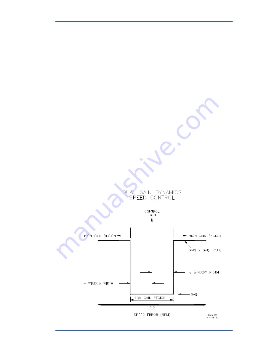
05 WINDOW WIDTH 1 (RPM)
dflt = 60.00 (1.00
–200.00)
This is the magnitude (in rpm) of speed error at which the control automatically
switches to fast response. The control uses the absolute value of speed error to
make this switch. The absolute value is the difference between the speed
reference and the speed. A window width that is too narrow results in cycling that
always factors in the gain ratio (see Figure 4-2).
06 GAIN RATIO 1
dflt = 1.00 (1.00
–10.00)
The ratio of the gain setting at steady state to the gain setting during transient
conditions. The gain ratio operates in conjunction with the window width and gain
adjustments by multiplying the gain set point by the gain ratio when the speed
error is greater than the window width. This makes the control dynamics fast
enough to minimize engine-speed overshoot on start-up and to reduce the
magnitude of speed error when loads are changing. This allows a lower gain at
steady state for better stability and reduced steady-state actuator linkage
movement (see Figure 4-2).
Figure 4-2. Control Gain as a Function of Speed Error
Содержание 2301E
Страница 14: ...2301E Digital Control Manual 26641 4 Woodward Figure 1 1a 2301E Outline Drawing Ordinary Locations...
Страница 15: ...Manual 26641 2301E Digital Control Woodward 5 Figure 1 1b 2301E Outline Drawing Hazardous Locations...
Страница 16: ...2301E Digital Control Manual 26641 6 Woodward Figure 1 2a 2301E Control Wiring Diagram sheet 1...
Страница 17: ...Manual 26641 2301E Digital Control Woodward 7 Figure 1 2b 2301E Control Wiring Diagram sheet 2...
Страница 18: ...2301E Digital Control Manual 26641 8 Woodward Figure 1 2c 2301E Control Wiring Diagram notes...
Страница 80: ...2301E Digital Control Manual 26641 70 Woodward This screen shows an example of the Final Settings...
Страница 100: ...2301E Digital Control Manual 26641 90 Woodward Figure 4 5 Typical Transient Response Curves...
Страница 181: ...Manual 26641 2301E Digital Control Woodward 171 Declarations...