


Manual 26641
2301E Digital Control
Woodward
55
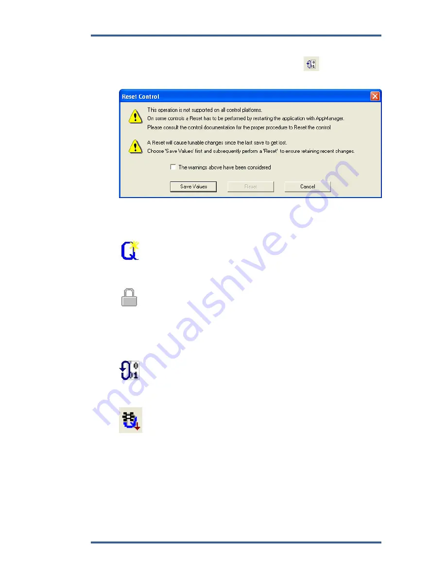
Step 13:
The control needs to be re-
booted using the “Reset” icon
. This show the
Reset Control pop up window:
Read the warnings and put a check mark in the selected box. Select Save
Values first, then Reset.
Listed below is a description of the icons in the Control Assistant software:
Allows for automatic generation of the WinPanel. Click on the
Q
icon
(Quick Inspector) on the tool bar. A Sheet will automatically be created form each
Service and Configure Header programmed into the control.
To enter the
I/O Lock
mode and enable a configure value to be entered,
click on the I/O Lock icon on the Tool Bar. Because the values set in Configure
are critical to engine operation, it is not safe to operate the prime mover while
these parameters are being configured. In the Configure mode the control
outputs will be set to their off state, and the microprocessor will stop executing
the application code. The control will have to be Reset to continue operation.
The
Reset
icon allows the microprocessor to store the configure
parameters, to return the outputs to their active state, and to resume executing
the application software.
Receive Quick Service/Configure Tunable List is selected to capture
Quick Service/Configure tunables, currently in the Control, into a tunable list
window. After receiving the list, a tunable list window is displayed and loaded
with the received tunable list. The tunables are received according to the
selections in the Communications dialog.
Содержание 2301E
Страница 14: ...2301E Digital Control Manual 26641 4 Woodward Figure 1 1a 2301E Outline Drawing Ordinary Locations...
Страница 15: ...Manual 26641 2301E Digital Control Woodward 5 Figure 1 1b 2301E Outline Drawing Hazardous Locations...
Страница 16: ...2301E Digital Control Manual 26641 6 Woodward Figure 1 2a 2301E Control Wiring Diagram sheet 1...
Страница 17: ...Manual 26641 2301E Digital Control Woodward 7 Figure 1 2b 2301E Control Wiring Diagram sheet 2...
Страница 18: ...2301E Digital Control Manual 26641 8 Woodward Figure 1 2c 2301E Control Wiring Diagram notes...
Страница 80: ...2301E Digital Control Manual 26641 70 Woodward This screen shows an example of the Final Settings...
Страница 100: ...2301E Digital Control Manual 26641 90 Woodward Figure 4 5 Typical Transient Response Curves...
Страница 181: ...Manual 26641 2301E Digital Control Woodward 171 Declarations...