


Manual 26641
2301E Digital Control
Woodward
39
The 2301E has a droop tracking feature which allows the control to constantly
monitor the system load. If the unit is in isochronous mode, and the unit is
switched to the droop mode, the unit will maintain the current load level and also
maintain the current engine speed (rpm). Once in the droop mode, if load
changes, then speed / frequency will also change.
Power System Management Concepts
This section provides a summary review of droop, isochronous,
droop/isochronous, isochronous load sharing, and base load operating concepts.
These concepts provide an understanding for power management.
Paralleling
There are two basic methods used for paralleling: droop, where speed decreases
with load increase, and isochronous, where speed remains constant with load
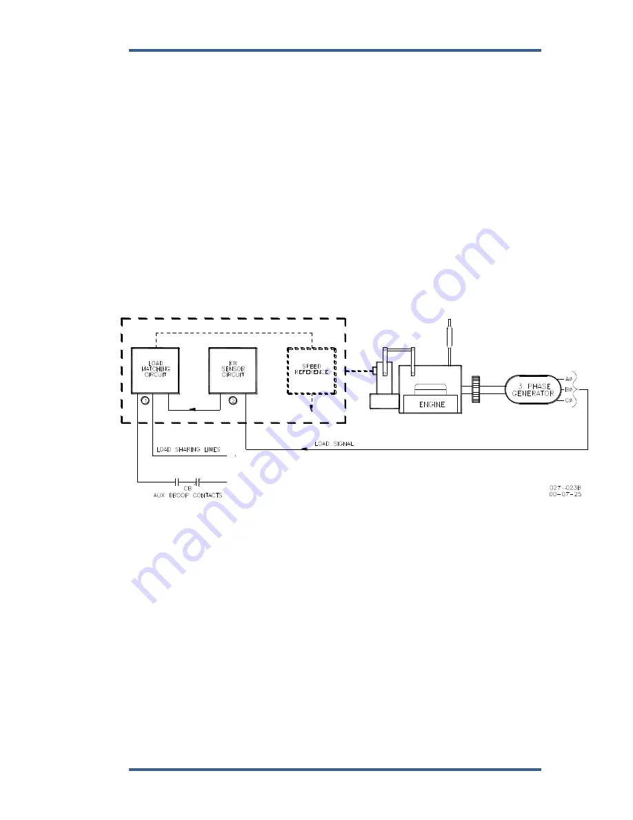
increase. The paralleling system shown in Figure 3-4 consists of a load matching
circuit (1), and kW sensor circuitry.
Figure 3-4. Paralleling System
An auxiliary contact on the generator breaker connected to the CB Aux discrete
input is used to select isochronous load control operation. A contact in series with
this auxiliary contact may be used to select either the droop or isochronous mode
of operation. When the input to the CB Aux contact is open, the control is in
droop. When the CB Aux contact is closed, the control is in isochronous load
control.
With only one unit on line, the generator picks up the available load and remains
at isochronous speed. If other units are on line and the load command discrete
input is open, the load will immediately load to the Unload Trip Level setting.
When the Load contact connected to terminal 40 is closed the load matching
circuit corrects the fuel output to proportion load.
The Load sensor computes the load carried by each phase of the generator. The
current load on each phase is multiplied by the cosine of the phase difference
between the current and the voltage, and the three phases are added to
determine the total load.
Содержание 2301E
Страница 14: ...2301E Digital Control Manual 26641 4 Woodward Figure 1 1a 2301E Outline Drawing Ordinary Locations...
Страница 15: ...Manual 26641 2301E Digital Control Woodward 5 Figure 1 1b 2301E Outline Drawing Hazardous Locations...
Страница 16: ...2301E Digital Control Manual 26641 6 Woodward Figure 1 2a 2301E Control Wiring Diagram sheet 1...
Страница 17: ...Manual 26641 2301E Digital Control Woodward 7 Figure 1 2b 2301E Control Wiring Diagram sheet 2...
Страница 18: ...2301E Digital Control Manual 26641 8 Woodward Figure 1 2c 2301E Control Wiring Diagram notes...
Страница 80: ...2301E Digital Control Manual 26641 70 Woodward This screen shows an example of the Final Settings...
Страница 100: ...2301E Digital Control Manual 26641 90 Woodward Figure 4 5 Typical Transient Response Curves...
Страница 181: ...Manual 26641 2301E Digital Control Woodward 171 Declarations...