Woodward 2301E Скачать руководство пользователя страница 71

Manual 26641 

2301E Digital Control 


Woodward 

61 

Step 5: 

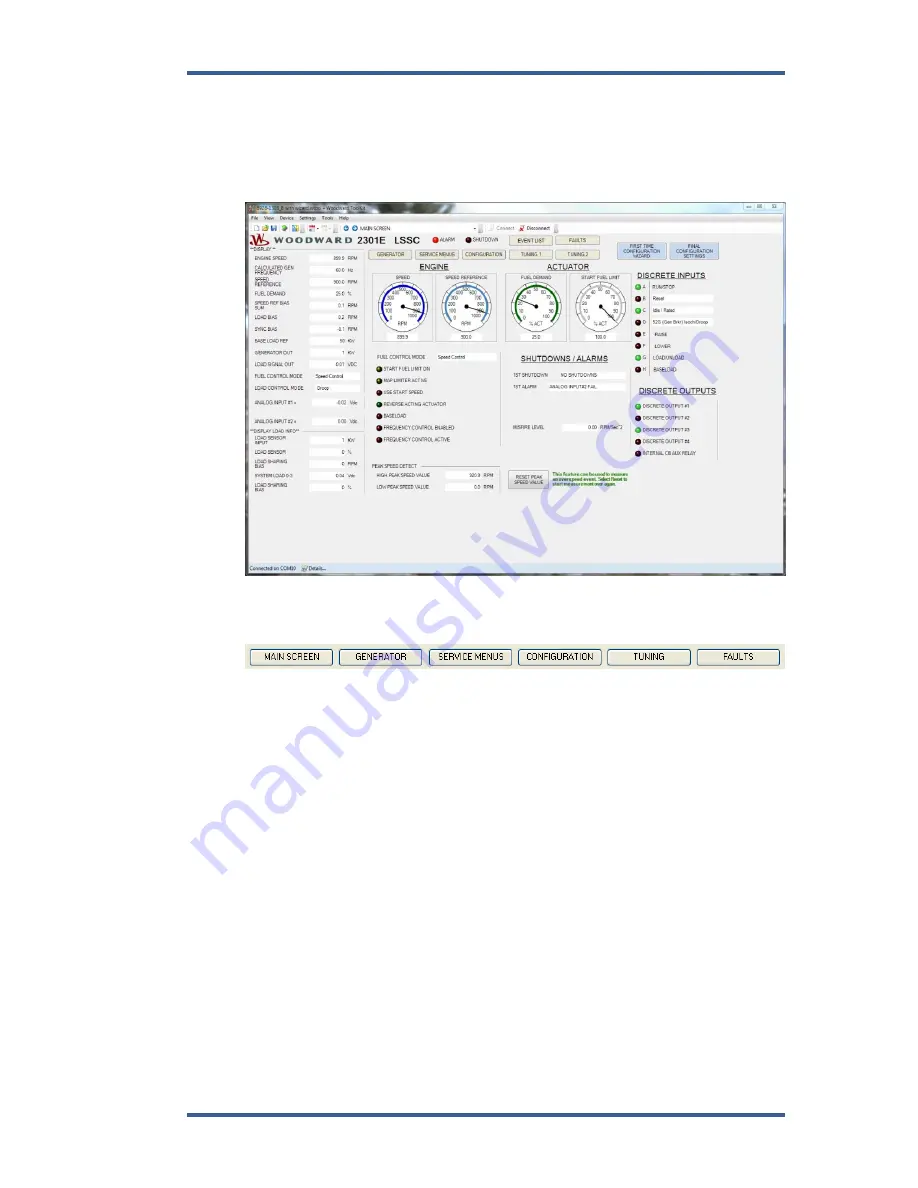
The first page is the 

“START UP” and displays information showing various 

engine functions including: Engine Speed and Speed Reference, Fuel Demand, 
Start Fuel Limit Level, Discrete Input and Output status, Fuel Control Mode, 
Shutdown / Alarm status, Analog Inputs, and a High Peak Speed value. Here is a 
view of the screen: 


Step 6: 

There are a number of ways to scroll through the different pages. The Navigation 
Buttons across the top: 


Содержание 2301E

Страница 1: ...ct Manual 26641 Revision K 7 2016 Original Instructions 2301E Digital Load Sharing and Speed Control for Engines 8273 1011 Ordinary Locations 8273 1012 Hazardous Locations Installation and Operation M...

Страница 2: ...age to the equipment Any such unauthorized modifications i constitute misuse and or negligence within the meaning of the product warranty thereby excluding warranty coverage for any resulting damage a...

Страница 3: ...or Minimum Fuel Terminal 34 15 Discrete Inputs B C D Terminals 35 36 37 15 Failed Speed Override 16 Reset 16 Select 2nd Dynamics 16 Shutdown External 16 Idle Rated Speed 17 Idle Rated Software Switch...

Страница 4: ...Mode 71 Configure Menu Descriptions 71 Exiting the Configure Mode 80 Service Menu Descriptions 80 Saving the Tunable Values 116 CHAPTER 5 INITIAL CONTROL SETTINGS 117 Initial Prestart Settings 117 St...

Страница 5: ...ION CHART 147 Configure Menus 147 Service Menus 148 APPENDIX B PID EXAMPLES 155 PID Conversion Charts 156 APPENDIX C MODBUS COMMUNICATION LIST 158 APPENDIX D SOFTWARE REVISION 161 APPENDIX E PRINTING...

Страница 6: ...1 Null Modem Cable 48 Figure 4 1 Null Modem Cable 58 Figure 4 2 Control Gain as a Function of Speed Error 87 Figure 4 3 Control Gain as a Function of Fuel Demand Load 88 Figure 4 4 Speed Filter 89 Fi...

Страница 7: ...over control system An overtemperature or overpressure shutdown device may also be needed for safety as appropriate Personal Protective Equipment The products described in this publication may present...

Страница 8: ...ed by improper handling read and observe the precautions in Woodward manual 82715 Guide for Handling and Protection of Electronic Controls Printed Circuit Boards and Modules Follow these precautions w...

Страница 9: ...North American Compliance These listings are limited only to those units bearing the appropriate CSA identification and marking CSA CSA Certified for Class I Division 2 Groups A B C D T3 or T4 Hazardo...

Страница 10: ...aving jurisdiction Connect the ground terminal to earth ground Use supply wire rated for minimum 75 C Use signal wire rated for a minimum of 240 Vac Per EN 60079 15 2010 Device meets ATEX Zone 2 requi...

Страница 11: ...control is housed in a sheet metal chassis and consists of a single printed circuit board The 2301E is set up and configured through an external computer connected at the 9 pin connector RS 232 Port...

Страница 12: ...ate of change of the generator load we can anticipate a speed or frequency change This anticipation logic can temporarily bump the speed up or down to counter react the speed change due to load Servic...

Страница 13: ...Air Pressure limiter Torque Limiter Idle Fuel limiter Load Acceptance and Load Rejection limiter Generator Breaker Open Fuel Limiter Programmable Analog Output Programmable Discrete Outputs Programma...

Страница 14: ...2301E Digital Control Manual 26641 4 Woodward Figure 1 1a 2301E Outline Drawing Ordinary Locations...

Страница 15: ...Manual 26641 2301E Digital Control Woodward 5 Figure 1 1b 2301E Outline Drawing Hazardous Locations...

Страница 16: ...2301E Digital Control Manual 26641 6 Woodward Figure 1 2a 2301E Control Wiring Diagram sheet 1...

Страница 17: ...Manual 26641 2301E Digital Control Woodward 7 Figure 1 2b 2301E Control Wiring Diagram sheet 2...

Страница 18: ...2301E Digital Control Manual 26641 8 Woodward Figure 1 2c 2301E Control Wiring Diagram notes...

Страница 19: ...control read all of this chapter and Electrostatic Discharge Awareness at the beginning of this manual Be careful when unpacking the electronic control Check the control for signs of damage such as be...

Страница 20: ...an be easily installed in each terminal Wires for the fixed mounted power terminals should be stripped 5 6 mm 0 22 inch long Do not tin solder the wires that terminate at the terminal blocks The sprin...

Страница 21: ...ly sufficient however 1 10 nF 500 1500 V may be used or needed and 1000 pF 1 nF 1000 V is recommended The intent is to provide a low impedance path to earth for the shield at frequencies of 150 kHz an...

Страница 22: ...hase B to terminal 2 Phase C to terminal 3 The potential transformer secondary line to line voltage must produce 90 to 120 Vac or 200 to 240 Vac The PT and CT input connections are not needed if using...

Страница 23: ...gurable and 40 must be connected to terminal 31 to connect the Load Matching Circuit to the load sharing lines The load sharing lines must be wired to the external load control device The circuit brea...

Страница 24: ...switch contacts have too high a resistance when closed and should be replaced These terminals must be isolated from ground In systems that provide an external low voltage source to power the 2301E co...

Страница 25: ...switch or relay contacts are open the Minimum Fuel Function will immediately pull the fuel demand to zero Do NOT use the minimum fuel contact as part of any emergency stop sequence Discrete Inputs B C...

Страница 26: ...C SHUTDOWNS or Reset alarms in menu D ALARMS An automatic reset is given to clear any alarm or shutdown when the engine clears the MPU Failsafe speed typically 5 of rated speed If the alarm or shutdo...

Страница 27: ...D can be adjusted to set the delay time before rated is selected CB Aux Droop Contact The input switch or relay contact used to activate the Load Control connects to terminal 37 default This discrete...

Страница 28: ...ynamic terms to be used when the input is closed This command is normally used when the closed loop path needs two independent sets of dynamics The dual dynamics control function is enabled by the Ser...

Страница 29: ...inal 39 Discrete Input F This discrete input changes the control operation by decreasing the speed reference ramp when the CB Aux input is open and by decreasing the base load reference when in base l...

Страница 30: ...units can occur The CB Aux Droop Contact discrete input must be TRUE for the Base Load input to affect the control The logic function of this input can be modified to be normally open or normally clo...

Страница 31: ...inal 24 for analog input 2 Make sure the shield has continuity the entire distance to the SPM synchronizer but do not connect the shield to the synchronizer The shield must be insulated from all other...

Страница 32: ...inals 19 and 20 Connect the shield to terminal 21 chassis Do NOT configure Analog Inputs 1 and 2 for the same function Analog Input 2 Terminals 22 23 The function of this input is default for 3 Baselo...

Страница 33: ...lay driver 1 can be used as a PWM actuator driver or a relay driver depending on the selection of the Actuator Output in the Configure menu o When configured as a PWM power wiring configuration is dic...

Страница 34: ...t can be software configured to one of several control parameters These parameters include Engine Speed Engine Speed Reference Fuel Demand Generator Output System Load Percent Synchronizer Input Analo...

Страница 35: ...The connector must be secured to the 2301E to prevent contact with other circuits RS 232 See Figure 2 3 for cable connection 2301E 50 RXD TXD TXD RXD Figure 2 3 RS 232 Pin assignments for Serial Comm...

Страница 36: ...le shield If the total cabling is 30 m typical the preferred shield connection is to connect the shield to earth ground chassis at one point most critical port using a capacitor to terminate the shiel...

Страница 37: ...point Wiring Using Shielded Twisted pair Cable with a Separate Signal Ground Wire The SG signal ground connection is not required if signal ground is unavailable Figure 2 7 Alternate Multipoint Wiring...

Страница 38: ...el or steam rack is at the minimum position If the actuator lever gets to its minimum position before completely shutting off fuel or steam the control may not be able to shut down the prime mover cau...

Страница 39: ...ection senses the load carried by its generator and causes the loads of all generators in the system to be shared proportionally During parallel operation of two or more generator or a generator paral...

Страница 40: ...minimum actuator position may not permit prime mover shutdown For controls with actuator current of 20 to 160 mA minimum fuel is defined as Actuator current less than 10 mA for forward acting control...

Страница 41: ...w width e g during a load transient the control automatically increases gain by an adjustable ratio This increased gain produces a faster fuel response and quickly restores engine speed at the speed r...

Страница 42: ...engine speed reaches 95 of the speed reference and the PID is in control of the fuel demand for 1 second the Start Limit Function will immediately increase to a maximum value of 100 When engine speed...

Страница 43: ...ir pressure in the engine manifold This fuel limit prevents over fueling when air pressure is low A five breakpoint pressure curve is available Setting up this limiter will also prevent excessive smok...

Страница 44: ...s manner The idle speed set point is provided for engine warm up or cool down cycles Idle speed may be set equal to or less than the rated speed set point Idle is independent of the lower limit set po...

Страница 45: ...trol in this manner If a difference is detected between the present speed reference and the remote reference rpm value the present speed reference is ramped up or down at the increase or decrease rate...

Страница 46: ...ptions apply to two or more units paralleled on a common isolated bus or by accessory device with the utility Baseload descriptions apply to a unit paralleled with the utility or with one or more unit...

Страница 47: ...the infinite bus The capability of the engine generator must be considered when operating this way As an example consider two generators one capable of providing 1200 kW and one capable of providing 6...

Страница 48: ...ramp to internal base load reference T T T F T Base load ref will ramp toward rated load T T T T F Base load ref will ramp toward the unload trip level T T T T T Base load ref will ramp to value of r...

Страница 49: ...t 1 and kW sensor circuitry Figure 3 4 Paralleling System An auxiliary contact on the generator breaker connected to the CB Aux discrete input is used to select isochronous load control operation A co...

Страница 50: ...in percent of rated speed and is set by the load droop set point Droop Mode Droop is a decrease in speed or frequency proportional to load That is as the load increases the speed or frequency decreas...

Страница 51: ...oad it is supplying up to the full load capability of the generator set see Figure 3 6 This mode can be used on one generator set running by itself in an isolated system Figure 3 6 Isochronous Mode Th...

Страница 52: ...rates a fixed amount of power see Figure 6 7 The output power of the swing machine will change to follow changes in the load demand Maximum load for this type of system is limited to the combined outp...

Страница 53: ...sochronous system or for de rating or unloading a machine Base Load Base Load for a system paralleled to an infinite bus or utility is the same as base load in an isolated system The advantage of base...

Страница 54: ...position necessary to pick up the load This feature is used to help kick the speed control and react to the load before the speed starts dropping Figure 3 9 shows the effects of the Load Pulse logic 1...

Страница 55: ...the PT and CT signals connected to the 2301E These signals measure the actual kW Load coming into the control When the Load is greater than a preset value and the generator breaker opens the fuel dema...

Страница 56: ...2301E control on a prime mover The computer and Control Assistant or 2301E Toolkit Service Tool software is not required and not necessary for normal operation of the prime mover unless Modbus is bei...

Страница 57: ...Control Assistant software is available from the Woodward Inc website at http www woodward com software Type in Control Assistant into the first search engine and click on Search Click on Download to...

Страница 58: ...stallation program that will step you through the installation process NOTE If you do not have the Microsoft NET Framework 4 0 already installed on your PC install it from the Microsoft web site 3 Aft...

Страница 59: ...e steps to communicate with the control Step 1 Download the Control Assistant software from www woodward com software Go to Start Programs Woodward Control Assistant Control Assistant This is what the...

Страница 60: ...2301E Digital Control Manual 26641 50 Woodward Step 3 An OPC connection will appear Check the radio buttons as shown below and click on Connect...

Страница 61: ...1E Digital Control Woodward 51 Step 4 An OPC connection will be made Step 5 When the communication is complete the window should look as follows Step 6 Minimize the SOS Servlink OPC Server program don...

Страница 62: ...1 52 Woodward Step 7 Click on the icon in the Main Window This will open up a WinPanel window with all of the Service and Configure menu header tabs Step 8 The Configure and Service Menu Tabs are loca...

Страница 63: ...ftware To accomplish this connect to the control and select the Receive Quick Service Configure Tunable List with this icon This will upload the settings and allow you to save them on your computer as...

Страница 64: ...same steps are applied Not all of the settings from the 2301D are compatible with the 2301E and list will be generated with the settings that cannot be loaded That list is shown below These items nee...

Страница 65: ...e the values set in Configure are critical to engine operation it is not safe to operate the prime mover while these parameters are being configured In the Configure mode the control outputs will be s...

Страница 66: ...f the preferred transfer protocol OPC is not selected To send a tunable list to a control the control must be in IO Lock Follow these steps to save and reload the variables from the control Step 14 Co...

Страница 67: ...red Select OK Step 17 Open the tc file that you saved by selecting File Open Click on the Send Tunable List icon The saved Tunable List will be sent to the control Step 18 Close the Tunable List file...

Страница 68: ...ort Figure 4 1 Null Modem Cable Figure 4 1 shows the required connections in the null modem cable These are the minimum connections some purchased null modem cables have more interconnects which are n...

Страница 69: ...If it does not connect verify the following 1 That you are using a Null Modem Cross over type cable 2 That the cable is connected to the correct port on your computer 3 That the cable is connected to...

Страница 70: ...301E Digital Control Manual 26641 60 Woodward Step 4 The left hand side of the each page of the ToolKit shows a Display Menu It is duplicated on each page of the 2301E Service Tool and looks like this...

Страница 71: ...tions including Engine Speed and Speed Reference Fuel Demand Start Fuel Limit Level Discrete Input and Output status Fuel Control Mode Shutdown Alarm status Analog Inputs and a High Peak Speed value H...

Страница 72: ...t And the Back to Startup buttons Step 7 The Save Values icon is very important It assures that when pressed the values in the 2301E are permanently saved to memory Failure to save the variables if ch...

Страница 73: ...led Offline Settings Editor and will read the settings or variables from the control NOTE Changing and applying and changes on the Offline Settings Editor pages will cause an I O Lock in the control w...

Страница 74: ...continue through each one until done Note The Service Menu variables can be adjusted while the engine is running Please be careful and understand the settings before making an adjustment Refer to the...

Страница 75: ...send a Reset pulse to the Alarms or Shutdowns If the Alarm or Shutdown is still active the will stay on the list Here is a screen shot of the Event List Step 14 The TUNING page allows the user to adju...

Страница 76: ...with the CB Aux discrete input check this box A trending tool is provided to view the various parameters The ENABLE BUMP and BUMP ACTUATOR feature is available to bump the actuator and watch the tran...

Страница 77: ...e and edit a wset file Step 18 First Time Configuration Wizard A new feature in revision C of the 2301E Toolkit Service Tool is the First Time Configuration Wizard and the Final Configuration Settings...

Страница 78: ...Digital Control Manual 26641 68 Woodward The Wizard will any or most of the tunable variables associated with setting the 2301E up for the first time This screen shows the particular sections of the W...

Страница 79: ...e 3 Actuator Output used as a low current PWM signal output 4 Torque Limiter Functions 5 Actuator Position Droop 6 Dual Dynamics 7 Frequency Control If you wish to use any of these features go to the...

Страница 80: ...2301E Digital Control Manual 26641 70 Woodward This screen shows an example of the Final Settings...

Страница 81: ...ge of the analog meters used in the 2301E Service Tool ToolKit 02 ENTER RATED SPEED 50 HZ in RPM dflt 750 0 4000 Set to the rated synchronous 50 Hz rpm of the engine generator if used The 2301E has th...

Страница 82: ...er is closed If set to False the speed could have a small error in it due to the speed bias 10 RST TO RATED INSTANT dflt TRUE TRUE FALSE This value when set to True will reset the speed bias to rated...

Страница 83: ...full engine revolution The last SAMPLES are averaged to determine the speed For example if SAMPLES 10 then the speed period is sampled every 1 10th of an engine revolution The speed is the average of...

Страница 84: ...er engine cycle Set this value to 1 for a two cycle engine and 2 for a four cycle engine 08 MAX ENGINE SPEED PERCENT dflt 120 30 400 This value is the maximum speed percentage that engine will run fro...

Страница 85: ...nce the loads automatically This value can be used to adjust the speed of a generator bus so that it can be synchronized to a utility bus 08 RSE LWR STOP IDL RTD RMP dflt TRUE FALSE TRUE If set TRUE t...

Страница 86: ...rameters for discrete output at terminal 45 same as parameters in 03 RELAY 1 ENERGIZES 06 RELAY 2 SELECTED FOR monitor Displays the relay function for terminal 45 07 RELAY 3 ENERGIZES 1 12 dflt 9 1 12...

Страница 87: ...ts the type of input used 1 4 20 mA 2 1 5 Volt 3 2 5 Volt 05 DISPLAY AI 1 TYPE monitor Displays the type of input for analog input 1 06 USE INPUT 1 FAIL TRIP dflt FALSE FALSE TRUE When set TRUE a fail...

Страница 88: ...ys incorporate a mechanical ballhead backup governor such as the Woodward EGB 04 SD ACT ON INTERNAL SD dflt TRUE FALSE TRUE Set to TRUE will cause the fuel demand to go to 0 on any internal shutdown F...

Страница 89: ...put is selected to TRUE the input will be ON or Energized when the contact is open and OFF or De energized when the contact is closed 01 SEL DI E ACTION dflt FALSE FALSE TRUE Selects the logic functio...

Страница 90: ...RPM monitor Displays the total speed bias into the summing junction 06 LOAD BIAS RPM monitor The speed bias for the load sharing and droop section of the control 07 SYNC BIAS RPM monitor The speed bia...

Страница 91: ...nitor This is the error signal to the speed reference from the load sharing 07 HIGH PEAK LOAD VALUE KW monitor This value is a peak value of how high the received generator load input got to It could...

Страница 92: ...own or the 12 RESET HIGH SPEED PEAK VALUE is reset 11 LOW PEAK SPEED VALUE monitor This value is a value of the how low the received engine speed input got to It will store the lowest value speed of t...

Страница 93: ...s exist Set for 4 20 mA 2 mA value 22 mA Set for 1 5 Vdc 0 001 Vdc value 5 5 Vdc Set for 2 5 Vdc 2 73 Vdc value 2 73 Vdc 05 LOAD SENSOR FAIL monitor When TRUE indicates a load sensor failure A Load Se...

Страница 94: ...inputs to and the outputs from the control 01 SPEED SENSOR INPUT RPM monitor Displays actual engine speed 02 LOAD SENSOR INPUT KW monitor Displays the generator load in kilowatts 03 ANIN 1 INPUT TYPE...

Страница 95: ...ed at which the engine operates at full load if the Droop mode is used or at the high limit of the speed trim function 03 LOWER SPEED LIMIT RPM dflt 800 00 0 00 4000 00 The minimum speed reference set...

Страница 96: ...nical load applications Speed undershoot may occur because the time required for the control to return to the new fuel setting is dependent on control dynamics and linkage adjustment 11 IDLE DROOP dfl...

Страница 97: ...OW WIDTH 1 RPM dflt 60 00 1 00 200 00 This is the magnitude in rpm of speed error at which the control automatically switches to fast response The control uses the absolute value of speed error to mak...

Страница 98: ...having high or low gain at low load levels This allows the Gain setting to be lower at light or no load for engine stability yet provide good control performance under loaded conditions see Figure 4 3...

Страница 99: ...TRUE then back to FALSE while the engine is operating in a normal steady state loaded or unloaded condition Figure 4 5 illustrates prime mover starts with the RAMP TIME set to minimum no ramp step lo...

Страница 100: ...2301E Digital Control Manual 26641 90 Woodward Figure 4 5 Typical Transient Response Curves...

Страница 101: ...speed control when the CB Aux Droop contact or Select 2nd Dynamics input is activated 03 DELAY DYN 1 ENABLE SEC dflt 0 00 0 00 20 00 This is the delay time before Dynamics 1 are used by the speed cont...

Страница 102: ...OINT 1C LD OR RPM dflt 99 80 0 01 5000 00 The load for breakpoint C 06 GAIN BREAKPOINT 1C dflt 2 0 0 001 100 00 This is the GAIN value when the load is at breakpoint C 07 BREAKPOINT 1D LD OR RPM dflt...

Страница 103: ...ine rpm 120 for 4 cycle engines firing frequency camshaft frequency x number of cylinders Initially set the filter frequency to the firing frequency As the filter frequency is reduced steady state sta...

Страница 104: ...20 00 A delay time in seconds that dynamics 1 will continue to be used by the speed control after the CB contact 03 DELAY DYN 1 ENABLE SEC dflt 0 00 0 00 20 00 The delay time that dynamics 2 will cont...

Страница 105: ...ody position of a gas engine is not linear in comparison to engine power output In naturally aspirated non turbocharged engines the position of the valve in comparison to engine output appears on a ch...

Страница 106: ...ming is needed whenever the gain of the engine and fuel system is non linear This usually occurs in gas engine applications A plot of the fuel system must be determined to properly adjust the gain of...

Страница 107: ...l demand as shown in Figure 4 8 Flat portions of the engine plot will require relatively small values of gain steep portions of the plot will require larger gain numbers actuator has to move a lot to...

Страница 108: ...e actuator 01 START FUEL LIMIT FD dflt 100 00 15 00 110 00 This limits the percent fuel demand when the engine is started The limit is usually set at the fuel level required to start the engine The li...

Страница 109: ...modes of operation 05 ENABLE IDLE LIMITER dflt FALSE FALSE TRUE Set to TRUE to enable the Idle Fuel Limiter Set to FALSE to disable the Idle Fuel Limiter This option when enabled will limit the Fuel D...

Страница 110: ...represents the torque limit breakpoint 15 TORQUE LIMIT BREAKPOINT 3 dflt 100 00 0 00 100 00 This sets the fuel demand at the speed breakpoint 1 16 MAX SPEED TORQUE LIMIT dflt 1500 00 0 00 4000 00 This...

Страница 111: ...D 0 100 TORQUE LIMITER FUNCTION FUEL DEMAND TORQUE LIMIT BREAK POINT SPEED BRKPOINT TORQUE LIMIT MAX SPEED TORQUE LIMIT Figure 4 11 Torque Limiter Function Figure 4 12 Dual Start Fuel Limit with Ramp...

Страница 112: ...RESSURE X4 dflt 15 000 1000 00 1000 00 This sets the pressure at the fourth breakpoint 09 MAP LIMIT Y4 dflt 100 000 0 00 100 00 This sets the maximum fuel demand at the fourth pressure setpoint 10 PRE...

Страница 113: ...voltage level of the load The value of 6 0 is typical for most analog load sharing schemes 03 LOAD SHARE GAIN dflt 1 000 0 01 10 00 Sets the load sharing gain A too high gain will result in unstable l...

Страница 114: ...BASELOAD LOWER TIME SEC dflt 60 000 1 00 600 00 The time for the reference to ramp from baseload maximum to baseload load minimum values entered above 13 UNLOAD TRIP LEVEL KW dflt 5 000 0 00 30000 00...

Страница 115: ...GURED FOR monitor This will display the function Analog Input 1 at terminal 19 21 was set for in the Configure mode 02 AI 2 CONFIGURED FOR monitor This will display the function Analog Input 2 at term...

Страница 116: ...input when used to bias speed from a remote control device The normal scale is 3 0 speed change per volt input The analog input range is 2 5 V 14 SYNC INPUT SCALE VOLT dflt 0 70 0 10 5 00 Sets the gai...

Страница 117: ...n selected for terminal 41 04 RELAY 1 ON LEVEL dflt 0 000 32000 00 32000 00 Enter the level switch ON setting in engineering units There is an ON and an OFF setting for each level switch option This a...

Страница 118: ...00 Enter the level switch OFF setting in engineering units must be less than the Relay On Level 16 RELAY 4 SELECTED AS monitor Displays the function selected for terminal 44 This relay is selected in...

Страница 119: ...ad 5 System Load 6 Analog Input 1 7 Analog Input 2 8 Speed Reference Bias 9 Baseload Reference kW 10 Misfire RPM 02 ANALOG OUTPUT SELECTION monitor Displays the analog output selection 03 4 mA OUTPUT...

Страница 120: ...l load sharing relay observe the green LED next to terminals 9 and 10 12 LOAD SHARE RELAY monitor Displays the status of the load share relay 13 ADJUST ANALOG OUTPUT dflt 0 000 0 00 100 00 Adjust 0 to...

Страница 121: ...be used for stability analysis if needed 01 DYNAMICS 2 ENABLED monitor Indicates the system is in the isochronous mode CB aux is closed and Dynamics 2 values are being used to the input of the PID co...

Страница 122: ...engine load changes in time If a large decrease in generator load is detected the speed reference is decreased momentarily to compensate for a large speed overshoot 02 LOAD REJECT DERIV S dflt 10 00 1...

Страница 123: ...FALSE the Frequency Control feature This feature will enable a small integrator which will allow the grid frequency of an isolated or islanded system to be maintained within a very small percentage o...

Страница 124: ...a hardware fault of the serial RS 232 communication port 03 PORT 1 BAUD RATE dflt 12 8 12 Sets the Baud rate which defines the transfer rate for port communications 8 9600 9 19200 10 38400 11 57600 1...

Страница 125: ...s 1 7 2 8 17 PORT 2 DATA BITS ARE SET FOR monitor Shows the selected data bits 18 PORT 2 STOP BITS dflt 1 1 3 Sets the Stop bits which defines the number of stop bits for the communications protocol S...

Страница 126: ...ERROR monitor Will indicate a TRUE when an exception error such as illegal command is detected 27 PORT 2 TOTAL EXCEPTION ERRORS monitor Is a count of the total exception errors 28 ENABLE ANALOG INPUT...

Страница 127: ...ine prime movers Set the ACTUATOR COMPENSATION at 0 35 for carbureted gas or gasoline prime movers 11 Set GAIN RATIO 1 to 1 0 to disable the effect of window width and gain ratio 12 ACCEL RAMP TIME Se...

Страница 128: ...s been verified No further adjustment when the engine is running will be necessary 5 Check the speed sensor Minimum voltage required from the speed sensor to operate the electronic control is 1 0 Vrms...

Страница 129: ...f a slow periodic instability remains slightly increase the ACTUATOR COMPENSATION and repeat the GAIN and RESET adjustments Continue to increase the ACTUATOR COMPENSATION and readjust the GAIN and RES...

Страница 130: ...urrent Transformer CT Phasing Check This control contains internal current transformers Due to their low impedance shorting their inputs is not effective The current input must be removed from the con...

Страница 131: ...acing through the wiring is the only means of correcting the current transformer phasing The highest positive reading of kW or Load Signal Out will be obtained when the CTs are correctly matched to th...

Страница 132: ...ervice Tool Observe 03 Gen Output READ KW Load Sensor calibration and monitoring Since the kW calibration cannot be completed until the phasing is correct the value shown is for reference only The Loa...

Страница 133: ...t the B phase CT and connect the B phase CT wires to terminal 6 and 7 20 Un short B phase CT apply full load and measure the load signal Start a new list and record this reading 21 Unload the system s...

Страница 134: ...units can be corrected by adjusting the Load Gain Increasing the LOAD GAIN will cause that generator to carry less load If stability problems occur when paralleled at a particular load signal reading...

Страница 135: ...hat you will be very close to the point of instability You are likely to adjust the gain a little bit too far and go into an unstable condition When that happens you will see the engine start to run a...

Страница 136: ...tch back to 1st dynamics Keep slightly adjusting the gain up or down until you find the setting that gives you the point of marginal stability When you are there the oscillations will neither decrease...

Страница 137: ...with negligible overshoot 17 This usually concludes the dynamic adjustment for one set of dynamics These settings are typically robust Overly aggressive adjustments should be avoided if possible The...

Страница 138: ...es Gain may be skipped in favor of Window Width and Gain Ratio adjustments only Figure 6 4 Trend Tool Trace Example 4 20 Figure 5 4 shows the transient response with the Gain Ratio and Window Width di...

Страница 139: ...highest Gain Ratio without going unstable If the Gain Ratio setting that causes severe instability is known then the final setting should not be more than half of this amount 24 Eventually a point is...

Страница 140: ...le personal injury loss of life or property damage Control Start up When the control is powered on the CPU begins execution of a section of the software program known as the boot code This code perfor...

Страница 141: ...d and should be replaced Discrete Inputs Do the following test to verify the function of the discrete inputs Do NOT do this test with the engine running 1 Repeat this step for all discrete inputs Clos...

Страница 142: ...going to Start Fuel value when cranking check to see Engine Speed is reading cranking speed If Fuel Demand is reading 0 increase the Start Fuel Limit Actuator or linkage Check actuator and linkage for...

Страница 143: ...e engine turbine or other type of prime mover to protect against runaway or overspeed with possible personal injury loss of life or property damage Faulty 2301E control Replace Prime mover overspeeds...

Страница 144: ...erence with the LOW IDLE SPEED setting when the prime mover is hot The LOW IDLE SPEED setting may be below the minimum fuel position of the actuator or prime mover fuel stop In this case the output vo...

Страница 145: ...will cause instability if picked up by lines associated with the amplifier summing point such as external speed trim paralleling lines droop contact magnetic pickup lines and synchronizer input The fo...

Страница 146: ...ing visually determine if actuator shaft is at maximum position If it is not an actuator problem is indicated or the linkage or fuel system is restricted Unequal speed settings Be sure that speed sett...

Страница 147: ...s allows the 2301E to be monitored but not controlled from an external device By simply connecting a monitoring device configured to communicate through Modbus and to the 2301E s defaulted protocol se...

Страница 148: ...E control is programmed to function as a slave unit only As a slave unit the 2301E will only respond to a transaction request by a master device The 2301E can directly communicate with a DCS or other...

Страница 149: ...errors or invalid data If there is invalid data in the message an error code is sent back to the master and the control issues an alarm message The error codes are defined in the following table If th...

Страница 150: ...constant before being sent by the 2301E See Appendix B for the default communication constants and ranges Boolean Writes Boolean Writes are logic signals that are writable to the 2301E control An exa...

Страница 151: ...01E supports Modbus function codes 3 6 and 16 These correspond to reading selected holding registers writing to a single holding register and writing to multiple holding registers respectively Appendi...

Страница 152: ...rough the Modbus The open close of contact inputs RUN SHUTDOWN etc serve as the independent command in Modbus BW These commands operate as a momentary input Which means the input from the Modbus comma...

Страница 153: ...also be handled through the OEM or Packager Please review your equipment system documentation for details Woodward Business Partner Support Woodward works with and supports a global network of indepen...

Страница 154: ...option is applicable to mechanical products only Returning Equipment for Repair If a control or any part of an electronic control is to be returned for repair please contact your Full Service Distribu...

Страница 155: ...oducts interface For information on these services please contact one of the Full Service Distributors listed at www woodward com directory Contacting Woodward s Support Organization For the name of y...

Страница 156: ...e of Fuel gas gaseous diesel dual fuel etc Power Output Rating Application power generation marine etc Control Governor Information Control Governor 1 Woodward Part Number Rev Letter Control Descripti...

Страница 157: ...ENTER NUMB OF CYLINDERS 8 1 24 04 ENTER FAILED SPD SENSE 5 0 2 0 50 0 05 MPU ALARM ARM TIME 10 0 120 06 ENTER RATED MAX LOAD KW 500 10 30000 07 2 CYCLE OR 4 CYCLE 1 1 2 08 MAX ENGINE SPEED PERCENT 120...

Страница 158: ...CYCLE MIN LIMIT 10 0 100 09 DUTY CYCLE MAX LIMIT 90 0 100 G DISCRETE IN ACTION 01 SEL DI A ACTION FALSE TRUE FALSE 02 SEL DI B ACTION FALSE TRUE FALSE 03 SEL DI C ACTION FALSE TRUE FALSE 04 SEL DI D A...

Страница 159: ...RESET SHUTDOWNS FALSE TRUE FALSE D ALARMS 01 ALARM STATUS Monitor 02 FIRST ALARM Monitor 03 ANALOG INPUT 1 FAIL Monitor 04 ANALOG INPUT 2 FAIL Monitor 05 LOAD SENSOR FAIL Monitor 06 LOAD SHARE LINE FA...

Страница 160: ...PID DYNAMICS IN USE Monitor I DYNAMICS 2 01 ENABLE DYNAMICS 2 w CB FALSE TRUE FALSE 02 DELAY DYN 2 ENABLE SEC 0 00 0 00 20 00 03 DELAY DYN 1 ENABLE SEC 0 00 0 00 20 00 04 PROP GAIN 2 2 000 0 001 100...

Страница 161: ...50 00 110 00 05 ENABLE IDLE LIMITER FALSE TRUE FALSE 06 IDLE FUEL LIMITER FD 100 00 0 00 100 00 07 ENABLE TORQUE LIMITER FALSE TRUE FALSE 08 MIN SPEED TORQUE LIMIT 300 00 0 00 4000 0 09 TORQUE LIMIT...

Страница 162: ...G INPUTS SETTINGS 01 AI 1 CONFIGURED FOR Monitor 02 AI 2 CONFIGURED FOR Monitor 03 SPEED w RMT IN MIN RPM 800 000 0 00 4000 00 04 SPEED w RMT IN MAX RPM 1000 000 0 00 4000 00 05 RMT SPEED REF INPUT RP...

Страница 163: ...5 TURN ON DO2 FALSE TRUE FALSE 06 DISCRETE OUTPUT 2 Monitor 07 TURN ON DO3 FALSE TRUE FALSE 08 DISCRETE OUTPUT 3 Monitor 09 TURN ON DO4 FALSE TRUE FALSE 10 DISCRETE OUTPUT 4 Monitor 11 TURN ON CB AUX...

Страница 164: ...OFTWARE REVISION Monitor 03 APPLICATION NAME Monitor Z COMM PORTS 01 ENABLE MODBUS CONTROL FALSE TRUE FALSE 02 PORT 1 FAIL Monitor 03 PORT 1 BAUD RATE 10 1 10 04 PORT 1 BAUD RATE IS SET FOR Monitor 05...

Страница 165: ...verspeed with possible personal injury loss of life or property damage This list only contains a small sample of engines Your engine make and model may not be listed If you want to put the PID values...

Страница 166: ...rop Gain Reset and Actuator Compensation values in the 2301E Figure B 1 Gain Potentiometer Conversion Chart Figure B 2 Reset Potentiometer Conversion Chart 0 2 4 6 8 10 12 14 16 18 20 0 1 2 3 4 5 6 7...

Страница 167: ...oodward 157 Figure B 3 Actuator Compensation Potentiometer Conversion Chart 0 0 1 0 2 0 3 0 4 0 5 0 6 0 7 0 8 0 9 1 0 1 2 3 4 5 6 7 8 9 10 2301D Value 2301A Act Comp Potentiometer Position 0 CCW 10 CW...

Страница 168: ...er Speed Load 0 0010 Isochronous Mode 0 0011 Droop Mode 0 0012 Load 0 0013 Unload 0 0014 Baseload ON 0 0015 Baseload OFF 0 0016 Select 2nd Dynamics 0 0017 De Select 2nd Dynamics 0 0018 External Modbus...

Страница 169: ...22 Discrete Input A State 1 0023 Discrete Input B State 1 0024 Discrete Input C State 1 0025 Discrete Input D State 1 0026 Discrete Input E State 1 0027 Discrete Input F State 1 0028 Discrete Input G...

Страница 170: ...08 Analog Input 1 3 0009 Analog Input 2 3 0010 Speed Bias RPM 3 0011 Engine Load 3 0012 Baseload Reference kW 3 0013 Load Bias RPM 3 0014 Sync Bias RPM 3 0015 Load sharing Bias 3 0016 Remote Speed Set...

Страница 171: ...ENABLE ANALOG INPUT W MODBUS This variable supports the logic change listed in 3 above 6 Added two Modbus Boolean write statements to Enable and Disable the Modbus Control 7 Changed the analog input...

Страница 172: ...if this were Inhibited Application Software 5418 6350 E Released May 2015 Software Modifications 1 Fixed issue with Idle Speed Reference When 50 Hz was selected the Idle Speed was not selected 2 Fixed...

Страница 173: ...ions over Modbus and still use a remote analog input speed reference 7 On the Service Y Communications page added all of the Modbus Write variables to help troubleshoot ToolKit Software 8928 1303 B Re...

Страница 174: ...oll to the right and find Service Menu Z COMM PORTS Menu number 11 PORT 2 SELECT MODBUS OR DATALOG should be changed to a 2 Menu number 12 PORT 2 IS SELECTED FOR should say Datalog 4 Scroll back to SE...

Страница 175: ...4 On the right hand side of the Main Screen is a button for the First Time Configuration Wizard Press this button to configure the control 5 Once finished with the Configuration Wizard go back to the...

Страница 176: ...the OPC Connection window opens make sure that the Servlink OPC Server and Local Server radio buttons are selected Click on Connect 4 Click on the icon or select Transfer Receive Quick Service Config...

Страница 177: ...ill not run at the right speed 13 To manually enter the above values with the Control Assistant software running select the icon Generate Quick Service Configure Sheets Manually go to each menu item l...

Страница 178: ...ty to tune the PID dynamic adjustments of the engine and use the PT CT inputs for load sharing droop baseload and isochronous baseload operations 1 0 Connect the ADEM control to Terminal 44 of the 230...

Страница 179: ...20 mA 4 20 or 0 200 mA to actuator software configurable Analog Output 0 20 or 4 20 mA internally powered configurable power by external 12 Vdc or 24 Vdc source max output current 200 mA Discrete Outp...

Страница 180: ...3 phase PT Burden in Specifications section to 90 240 Vac line to line 45 66 Hz Changes in Revision D Various corrections to values as marked pages 2 21 22 69 70 77 Added explanation of 5418 6350 C so...

Страница 181: ...Manual 26641 2301E Digital Control Woodward 171 Declarations...

Страница 182: ...2 1519 USA 1000 East Drake Road Fort Collins CO 80525 USA Phone 1 970 482 5811 Email and Website www woodward com Woodward has company owned plants subsidiaries and branches as well as authorized dist...

Отзывы: