Analog-to-digital converters (ADC)
RM0365
299/1080
DocID025202 Rev 7
15.3.9 ADC
on-off
control (ADEN, ADDIS, ADRDY)
First of all, follow the procedure explained in
Section 15.3.6: ADC voltage regulator
).
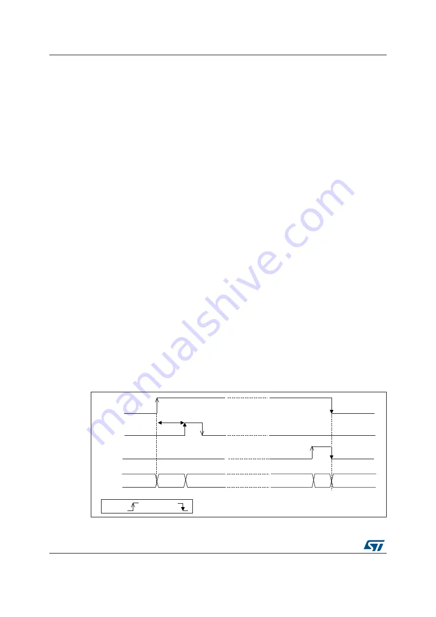
Once ADVREGEN[1:0] = 01, the ADC can be enabled and the ADC needs a stabilization
time of t
STAB
before it starts converting accurately, as shown in
. Two control bits
enable or disable the ADC:
•
ADEN=1 enables the ADC. The flag ADRDY will be set once the ADC is ready for
operation.
•
ADDIS=1 disables the ADC and disable the ADC. ADEN and ADDIS are then
automatically cleared by hardware as soon as the analog ADC is effectively disabled.
Regular conversion can then start either by setting ADSTART=1 (refer to
Conversion on external trigger and trigger polarity (EXTSEL, EXTEN, JEXTSEL, JEXTEN)
or when an external trigger event occurs, if triggers are enabled.
Injected conversions start by setting JADSTART=1 or when an external injected trigger
event occurs, if injected triggers are enabled.
Software procedure to enable the ADC
1.
Set ADEN=1.
2. Wait until ADRDY=1 (ADRDY is set after the ADC startup time). This can be done
using the associated interrupt (setting ADRDYIE=1).
Note:
ADEN bit cannot be set during ADCAL=1 and 4 ADC clock cycle after the ADCAL bit is
cleared by hardware(end of the calibration).
Software procedure to disable the ADC
1.
Check that both ADSTART=0 and JADSTART=0 to ensure that no conversion is
ongoing. If required, stop any regular and injected conversion ongoing by setting
ADSTP=1 and JADSTP=1 and then wait until ADSTP=0 and JADSTP=0.
2. Set
ADDIS=1.
3. If required by the application, wait until ADEN=0, until the analog ADC is effectively
disabled (ADDIS will automatically be reset once ADEN=0).
Figure 57. Enabling / Disabling the ADC
06Y9
W
67$%
$'(1
$'5'<
$'',6
$'&
&RQYHUWLQJ&+
2))
E\+:
E\6:
5(4
2)
VWDW
2))
6WDUWXS
5'<
5'<


