4.8.1 Adjustment Procedures
238
4.8 Head Height Adjustment
VJ628XE-M-00
4.8
Head Height Adjustment
This section describes the procedure to check Carriage height (distance from the platen).
4.8.1
Adjustment Procedures
●
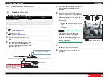
Tools & Jigs & Maintenance Parts
Name
No.
Remarks
Phillips screwdriver No.2
Generic
product
-
PG Adjusting Jig (1.1/1.3)
DG-43193 -
1
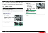
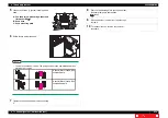
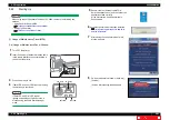
Remove R Side Cover.
2
Release Carriage lock.
3
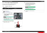
Place the Head height adjustment Jig on
Platen.
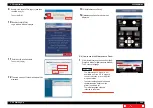
4
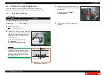
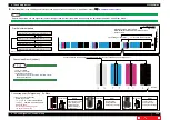
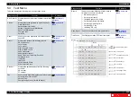
Check that Carriage can pass through a gap
above the 1.1mm part of the Head height
checking Jig and cannot pass through a gap
above the 1.3mm part.
*GCF
1.3mm
1.4mm
Head Height Adjustment Jig
Head Protector
L
R
Check the head height by whether
Print head goes through protruding
portions on both sides.
Slide Jig on Platen from the
both sides and check.
2NCVGP
Jig
5
Reverse the direction of the jig and adjust the
opposite side of the head with the same
procedure.
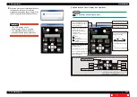
6
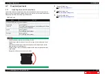
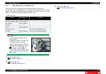
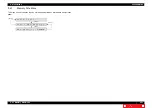
When Print head does not go through 1.1mm
step or go through 1.3
mm
, loosen the screws
(1 piece each on the right and left sides) that
retain the head adjustment cam located on the
right and left sides of the carriage, and adjust
the head height.
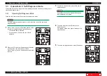
• Move the cam upward: Heighten the head
height.
• Move the cam downward : Heighten the
head height.
NOTE
The heights of right and left cams are
separately changed.After changing the
height, refer to the steps 4to 6 and make
sure to use Head height adjustment Jig to
check that the heights of the right and left
cams are appropriate.
7
Apply the Thread locker on the Head
adjustment cam to fix the head height.
8
To reassemble unit, reverse the removal
procedure.
Head adjustment cam
Heightens
Lowers
Heightens
Lowers

