3.8.15 Replacing Head
134
3.8 Replacing Cursor section
VJ628XE-M-00
3.8.15
Replacing Head
●
Tools & Jigs & Maintenance part
㨀㧵㧼
• This section describes the procedure to replace the maintenance part, Head
Assy.In this section, it is reffered to as Head.
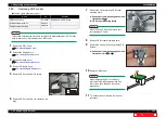
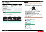
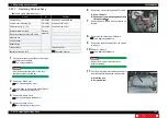
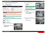
• Ink pipings are as shown below.
CAUTION
• During operation, make sure not to touch the nozzle surface of Head or let foreign
substances adhere.
• Print head Assy has been adjusted. Do not disassemble it.
• Do not touch board and tape cable which are already assembled on print head.
Moreover, do not touch around tape cable when assembling head cover.
• Before replacing the board or plugging/unplugging FFC, unplug Power cable and
leave it for a while. If operating with Power cable still plugged, Board may be
damaged or operators may get an electric shock by standby electricity.
• Before plugging FFC, check FFC terminal (to see the corner of the terminal is not
crooked and reinforcement is not peeled off).
• When plugging/unplugging FFC, do it vertically to the connector.
If plugged/unplugged obliquely, it may damage, shunt, or disconnect the
terminals inside the connector, and may damage the elements on the board.
• Make sure to plug FFC all the way.
• After plugging, make sure that FFC and connector terminal are aligned and that
FFC is not plugged obliquely.
Name
No.
Remarks
IA5540 Head Assy
DG-43988 Exploded View
CR
(
Head Base
)
Phillips screwdriver No.2
Generic
products
-
Phillips screwdriverNo.1
-
slotted screwdriver
-
ball point hexagonal wrench(2.5mm)
-
Longnose pliers
-
Plastic bag
Can be omitted
C Lc Cl Cl
K
Y
M
Lm
K Y M M
K
C
C
Y
C Lc WhMt
K
Y
M
Lm
4 color
6 color
8 color
C Lc WhWh
K
Y
M
Lm
7 color
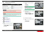
1
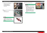
Perform ink discharge operation to discharge
ink entirely from ink path.
NOTE
After ink discharge operation, make sure
that Ink cartridge is pulled out.
2
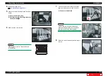
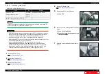
Removing R Side Cover.
3
Release Carriage Lock.
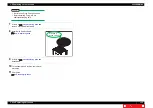
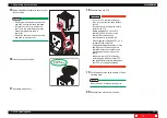
Head Board
ޓ
Head Nozzle
Tape wire

