background image

Extruder Gear Replacement Guide for the M3D PRO 


In this guide we will explain how to replace the extruder gear for your M3D PRO. You will need 
a 2.0mm/1.5mm hex screwdriver for the disassembly and you’ll want to be in a antistatic 
environment. Some electronics will be exposed during the disassembly and there is a chance 
you could damage them. We recommend not working on a carpeted area and to discharge 
before working. You can do this by touching something metal (Not the printer) for at least one 
second. Wearing an antistatic wrist-wrap would be good. Link for a wrist-wrap here 

https://www.amazon.com/Rosewill-Anti-Static-Components-RTK-002-
Yellow/dp/B004N8ZQKY/ref=sr_1_1?ie=UTF8&qid=1494531998&sr=8-1-
spons&keywords=anti+wrist+strap&psc=1


Although, it is highly recommended to use an antistatic wrist-wrap, if you do not have access 
to the antistatic wrist-wrap, you can do the repair process by having a metal contact to your 
body throughout the repair.


Since the M3D PRO 3D printer is highly static device as there are various PCBs involved, if the 
repair process is carried out without following the above recommendation and the customer 
end up frying the electronics, they would need to send back their printers to M3D headquarters 
for replacement.


Step 1. 

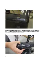
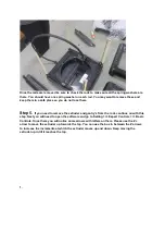
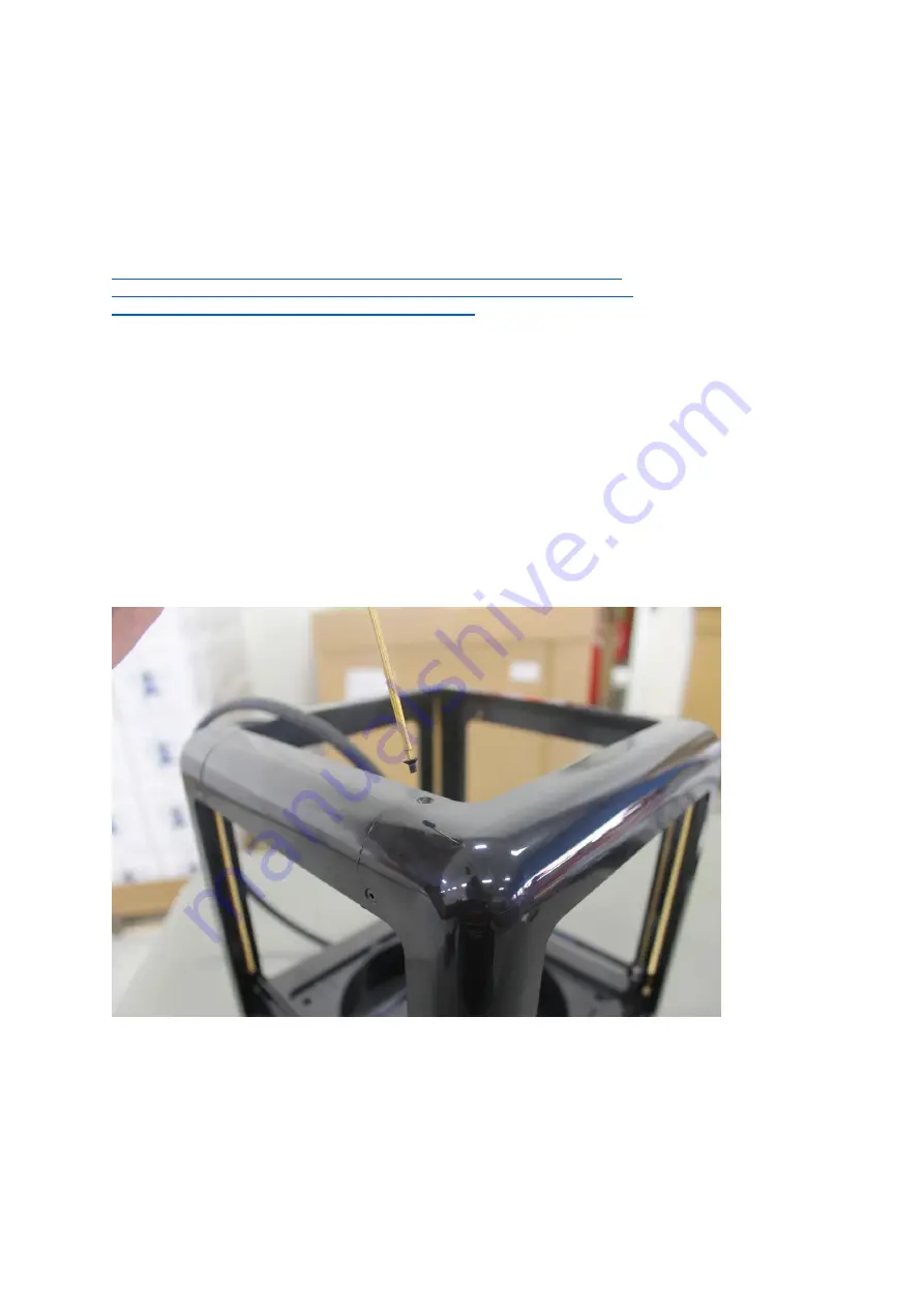
The first step will be to remove the front cover from the Pro. To do this you will need 

to remove the hex screws from the cover. There are a total of 8 screws in each cover. Four 
screws on the top and four screws on the bottom.  
 
1. 


Содержание PRO

Страница 1: ...w dp B004N8ZQKY ref sr_1_1 ie UTF8 qid 1494531998 sr 8 1 spons keywords anti static wrist strap psc 1 Although it is highly recommended to use an antistatic wrist wrap if you do not have access to the...

Страница 2: ...removed all of the screws you can gently start pulling the cover off the Pro Try pulling out the top a little first and then move onto the bottom Keep going back and forth from top to bottom until th...

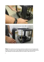
Страница 3: ...een removed move onto the rear cover The process will be similar to the front cover The only difference will be that there is a grommet attached to the cable assembly on the bottom that may need to be...

Страница 4: ...2 3...

Страница 5: ...4 5...

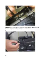
Страница 6: ...Step 4 Once the front and back covers are removed you will be left with the box top rails These can easily be removed by just lifting them up and off the rods 1 2...

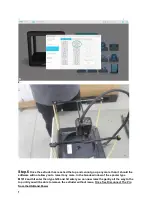
Страница 7: ...move the extruder and gantry s from the rods continue on with this step Next you will need to open the software and go to Setting Expert Controls Basic Controls Once there you will notice some arrows...

Страница 8: ...are will not allow you to raise it any more In the Gcode window of the spooler type M1012 and hit enter then type G33 and hit enter you can now raise the gantry all the way to the top until you will b...

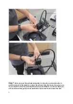
Страница 9: ...e able to pull the rods out of the sliders to remove the extruder from the X rods If you have one of our early Pro s then the rods might have been press fitted on To remove these you will need to twis...

Страница 10: ...2 3...

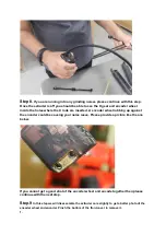
Страница 11: ...A encoder wheel rubbing up against the encoder could be causing your noise issue Please provide a picture like the one below If you cannot get a good shot of the encoder wheel and encode together then...

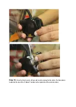
Страница 12: ...2 Step 10 Once the front cover is off you will need to unplug the fan cable The fan cable is located at the top of the X Board located on the right side of the extruder motor...

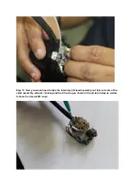
Страница 13: ...1 Now you would need to take the internal print head assembly out that consists of the cable assembly extruder housing and the X housing as shown in the picture below as well as remove the clear wallE...

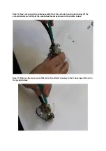
Страница 14: ...ly from the extruder housing but taking off the screw that sits on the top of the small sheet metal as shown in the picture below Step 13 Remove the two screws that joins the extruder housing to the X...

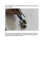
Страница 15: ...Step 14 Remove the nozzle subassembly in order to get access to screw that is hidden behind the black teflon tube teflon short as shown in the picture below...

Страница 16: ...er to loosen it as shown in the picture below Step 16 The next step would be take the extruder motor out so that the old extruder gear can be pulled out for replacement The extruder motor is removed a...

Страница 17: ......

Страница 18: ...Step 17 Now the extruder gear needs to pushed out of the extruder housing as shown in the picture below...

Страница 19: ...g when the old extruder gear was pushed out and thus is not shown in the picture below If that bearing comes out of the housing make sure that you place it back on the top of the new extruder gear and...

Страница 20: ...ing the extruder gear as shown in the above picture use the back of the screw driver to push the new extruder gear deep into the extruder housing such that it is pushed all the way back in as shown in...

Страница 21: ...at seats on the top of the extruder gear is pushed all the way back in as shown in the picture above shown by the red arrow Step 20 Now engage the extruder housing and the X housing back together as s...

Страница 22: ...Step 21 Lastly engage the cable assembly through the small sheet metal with its appropriate screw to the extruder housing as shown in the picture...

Страница 23: ...This is how the finally subassembly should look like once all the components extruder housing X housing and cable assembly are put together...

Отзывы: