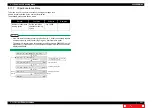
6.2.1 Starting Up
351
6.2 Operations in Maintenance Mode 2
VJ628XE-M-00
(2) Connecting Jig Panel Assy
NOTE
• When starting Self-diagnostic function or Maintenance mode 2, it is necessary to
connect Jig Panel Assy (maintenance parts) to the MAIN Board of the printer.
(Jig panel Assy is not enclosed by the printer.)
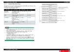
• Prepare Jig Panel Assy and Phillips screwdriver No.2.
(refer to the following table)
●
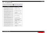
Tools & Jigs & Maintenance part
Name
No.
Remarks
Jig Panel Assy
DG-44954 the followings are enclosed
Panel FFC
Panel Unit
Panel Sheet
Phillips screwdriver No.2
Generic
product
-
3
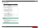
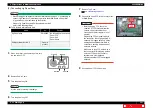
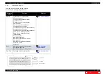
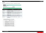
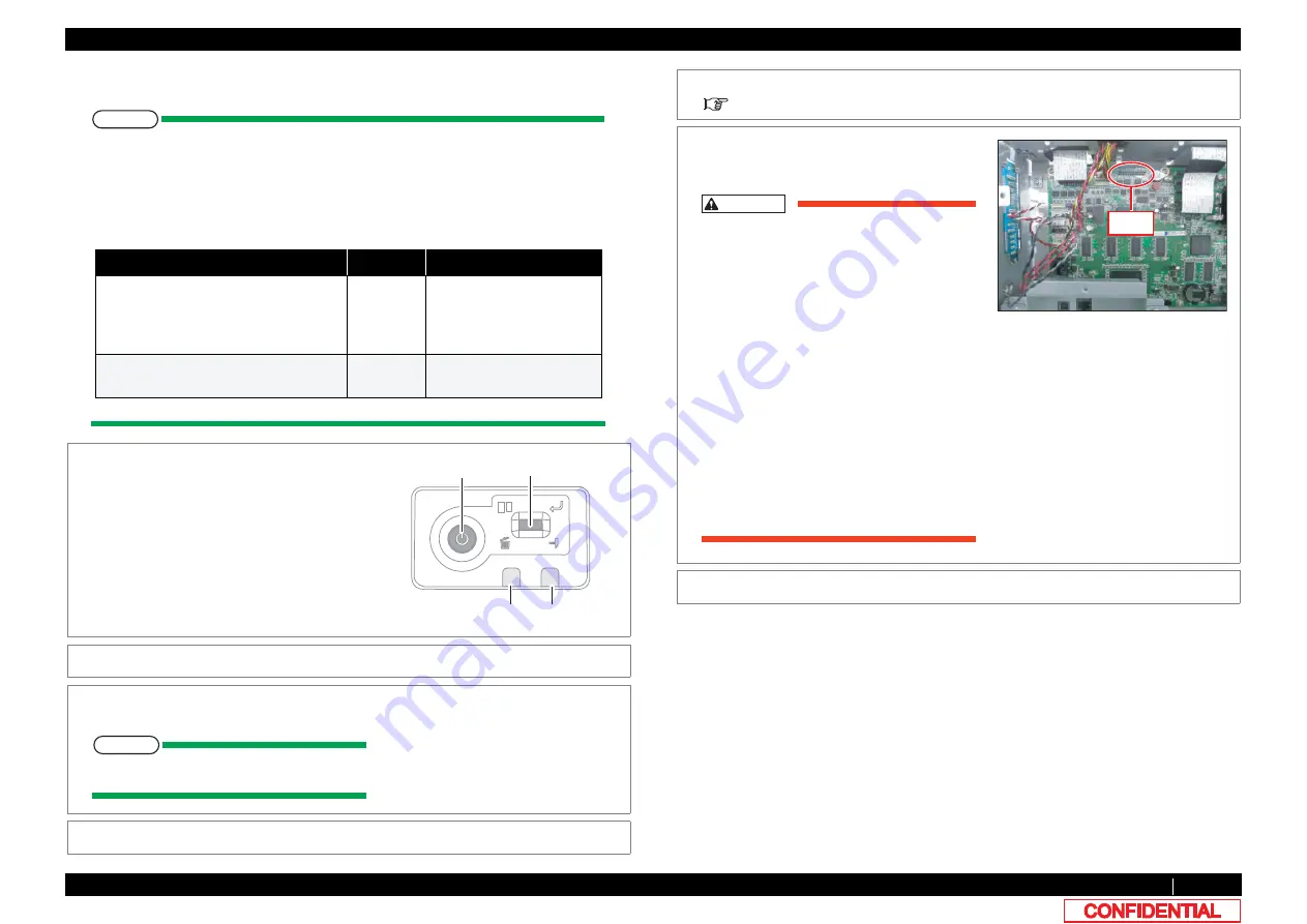
When the printer is an operating state, turn
the power key OFF.
4
Remove Power Cable.
5
Turn the power key ON.
NOTE
It is the work for making it discharge.
6
Turn the power key OFF.
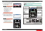
Error LED
Power key
Data LED
Multi key
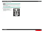
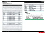
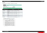
7
Remove Top Cover.
8
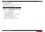
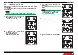
Connect the Panel FFC to the connector J33
of MAIN Board.
CAUTION
• Before plugging FFC, check the
condition of FFC terminals (that the
corners of the terminals are not
crooked and reinforcing plate is not
peeled).
• Plug/unplug FFC perpendicularly to
the connector. Never plug/unplug it
obliquely. If plugged obliquely, it may
damage/shorten/break terminals in
connectors, causing a breakdown of
on-board devices.
• Make sure to plug FFC all the way in
the connector. After plugging it, make
sure that FFC and the connector
terminals are not misaligned
sideways and that FFC is not plugged
obliquely.
9
Connect Panel FFC to Panel Unit.
J33

