3. SIGNALS AND WIRING
3 - 9
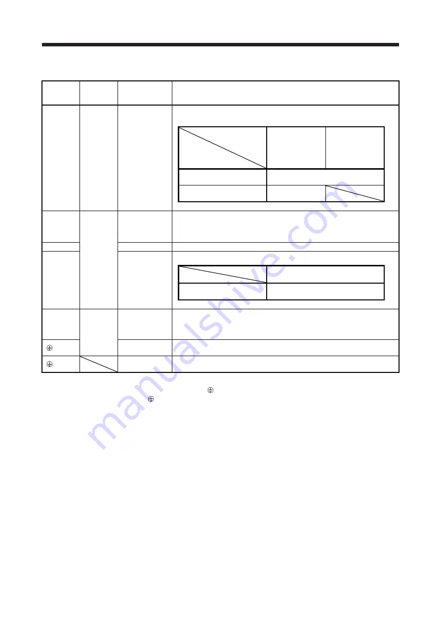
(2) Detailed explanation
Symbol Connector
Connection
destination
(application)
Description
L1/L2/L3 CNP1
Main circuit power
supply
Supply the following power to L1, L2, and L3. For 1-phase 200 V AC to 240 V AC,
connect the power supply to L1 and L3. Leave L2 open.
Servo amplifier
Power supply
MR-J4W2-22B
MR-J4W2-44B
MR-J4W2-77B
MR-J4W3-222B
MR-J4W3-444B
MR-J4W2-1010B
3-phase 200 V AC to 240 V
AC, 50 Hz/60 Hz
L1/L2/L3
1-phase 200 V AC to 240 V
AC, 50 Hz/60 Hz
L1/L3
P+/C/D
CNP2
Regenerative
option
When using a servo amplifier built-in regenerative resistor, connect P+ and D.
(factory-wired)
When using a regenerative option, connect the regenerative option to P+ and C.
Refer to section 11.2 for details.
N-
For manufacturer N- terminal is for manufacturer. Be sure to leave this terminal open.
L11/L21
Control circuit
power supply
Supply the following power to L11 and L21.
Servo amplifier
Power supply
MR-J4W2-22B to MR-J4W2-1010B
MR-J4W3-222B to MR-J4W3-444B
1-phase 200 V AC to 240 V
AC, 50 Hz/60 Hz
L11/L21
U/V/W
CNP3A
CNP3B
CNP3C
(Note 1)
Servo motor
power output
Connect them to the servo motor power supply (U, V, and W). Connect the servo
amplifier power output (U, V, and W) to the servo motor power input (U, V, and W)
directly. Do not let a magnetic contactor, etc. intervene. Otherwise, it may cause a
malfunction.
(Note 2)
Protective earth
(PE)
Connect the grounding terminal of the servo motor.
(Note 2)
Protective earth
(PE)
Connect to the protective earth (PE) of the cabinet to ground.
Note 1. For the MR-J4 3-axis servo amplifier
2. Connect the grounding terminal of the servo motor to of CNP3A, CNP3B, and CNP3C. For grounding, connect the
protective earth (PE) terminal ( ) of front lower part on the servo amplifier to the protective earth (PE) terminal on a cabinet.
Содержание MR-J4W2
Страница 9: ...A 8 MEMO ...
Страница 17: ...8 MEMO ...
Страница 31: ...1 FUNCTIONS AND CONFIGURATION 1 14 MEMO ...
Страница 95: ...4 STARTUP 4 20 MEMO ...
Страница 169: ...6 NORMAL GAIN ADJUSTMENT 6 20 MEMO ...
Страница 201: ...7 SPECIAL ADJUSTMENT FUNCTIONS 7 32 MEMO ...
Страница 213: ...8 TROUBLESHOOTING 8 12 MEMO ...
Страница 219: ...9 OUTLINE DRAWINGS 9 6 MEMO ...
Страница 229: ...10 CHARACTERISTICS 10 10 MEMO ...
Страница 295: ...13 USING STO FUNCTION 13 14 MEMO ...
Страница 327: ...14 USING A LINEAR SERVO MOTOR 14 32 MEMO ...
Страница 371: ...16 FULLY CLOSED LOOP SYSTEM 16 24 MEMO ...
Страница 521: ...APPENDIX App 38 ...
Страница 537: ...MEMO ...
Страница 541: ......

