17. APPLICATION OF FUNCTIONS
17 - 9
17.1.8 Change of specifications of "J3 compatibility mode" switching process
(1) Detailed explanation of "J3 compatibility mode" switching
(a) Operation when using a servo amplifier before change of specifications
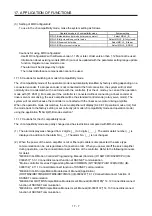
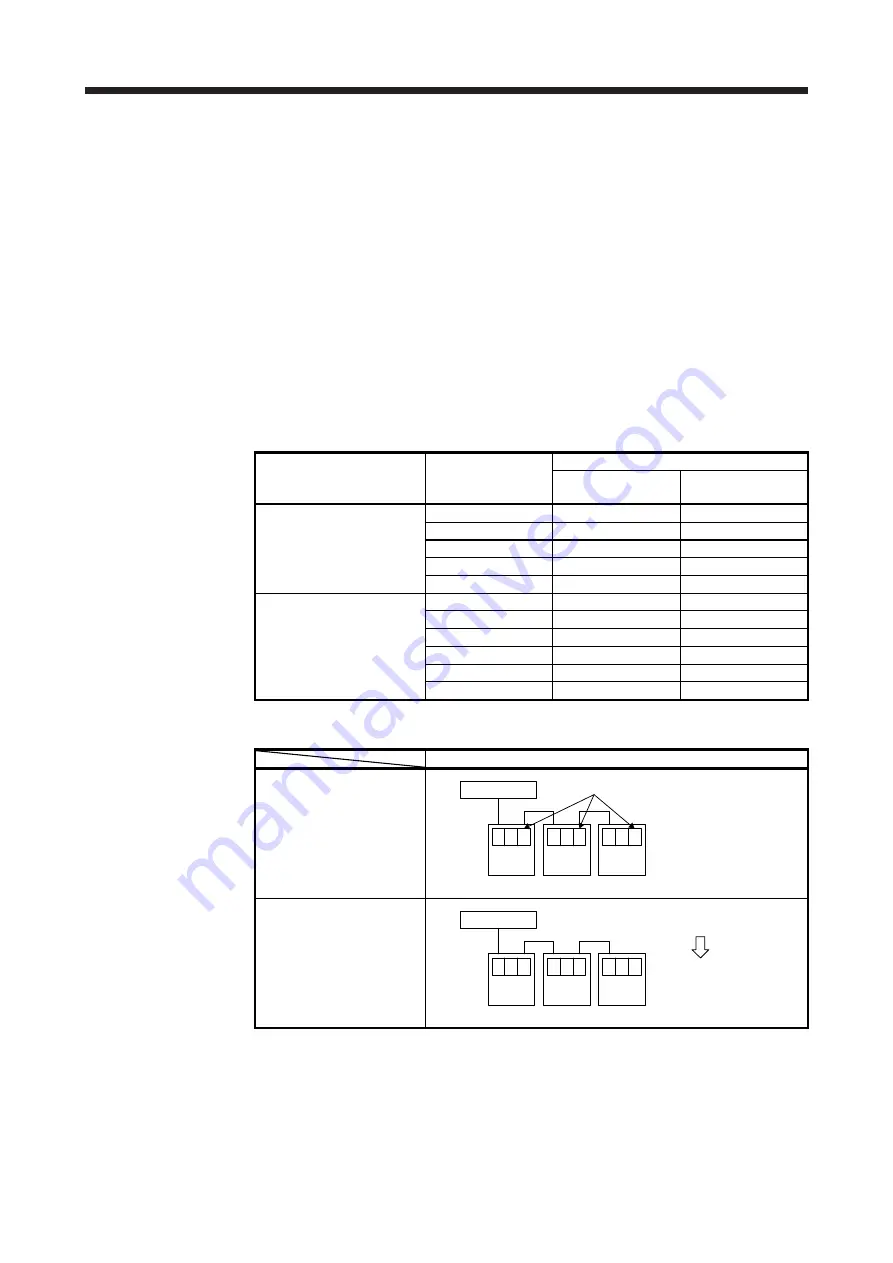
For the controllers in which "Not required" is described to controller reset in table 17.1, the mode will
be switched to "J3 compatibility mode" for all axes at the first connection. However, it takes about 10
s per axis for completing the connection.
For the controllers in which "Reset required" is described in table 17.1, the operation at the first
connection is shown in table 17.2. The LED displays will be "Ab." for all axes at the first connection
to the controller as shown in table 17.2. After that, resetting controller will change the 1-axis to "b01".
The 2-axis and later will not change from "Ab.". After that, one axis will be connected per two times
of controller reset.
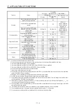
Table 17.1 Controller reset required/not required list (before change of
specifications)
Controller Model
Controller reset required/not required
Single-axis
connection
Multi-axis connection
Motion controller
R_MTCPU
Not required
Not required
Q17_DSCPU
Not required
Not required
Q17_DCPU
Not required
Not required
Q17_HCPU
Not required
Not required
Q170MCPU
Not required
Not required
Simple motion module
Positioning module
RD77MS_
Not required
Not required
QD77MS_
Not required
Not required
QD75MH_
Not required
Not required
QD74MH_
Reset required
Reset required
LD77MH_
Not required
Not required
FX3U-20SSC-H
Not required
Reset required
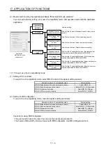
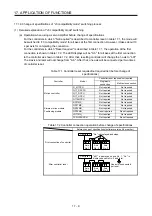
Table 17.2 Controller connection operation before change of specifications
Before change of specifications (software version A4 or earlier)
First connection of controller
Controller
Axis
No. 1
b .
A
Axis
No. 2
b .
A
Axis
No. 3
b .
A
"Ab." is displayed and stops
After controller reset
Controller
Axis
No. 1
0 1
b
Axis
No. 2
b .
A
Axis
No. 3
b .
A
"b01" is displayed on axis No. 1, "Ab." is
displayed on axis No. 2 and later.
One axis is connected
per reset.
Содержание MR-J4W2
Страница 9: ...A 8 MEMO ...
Страница 17: ...8 MEMO ...
Страница 31: ...1 FUNCTIONS AND CONFIGURATION 1 14 MEMO ...
Страница 95: ...4 STARTUP 4 20 MEMO ...
Страница 169: ...6 NORMAL GAIN ADJUSTMENT 6 20 MEMO ...
Страница 201: ...7 SPECIAL ADJUSTMENT FUNCTIONS 7 32 MEMO ...
Страница 213: ...8 TROUBLESHOOTING 8 12 MEMO ...
Страница 219: ...9 OUTLINE DRAWINGS 9 6 MEMO ...
Страница 229: ...10 CHARACTERISTICS 10 10 MEMO ...
Страница 295: ...13 USING STO FUNCTION 13 14 MEMO ...
Страница 327: ...14 USING A LINEAR SERVO MOTOR 14 32 MEMO ...
Страница 371: ...16 FULLY CLOSED LOOP SYSTEM 16 24 MEMO ...
Страница 521: ...APPENDIX App 38 ...
Страница 537: ...MEMO ...
Страница 541: ......

