18. MR-J4W2-0303B6 SERVO AMPLIFIER
18 - 34
18.3.8 Alarm occurrence timing chart
CAUTION
When an alarm has occurred, remove its cause, make sure that the operation
signal is not being input, ensure safety, and reset the alarm before restarting
operation.
When alarms are occurring in both axes of A and B, shut off the main circuit
power supply. Not doing so may cause a fire when a regenerative transistor
malfunctions or the like may overheat the built-in regenerative resistor.
POINT
In the torque control mode, the forced stop deceleration function is not available.
To deactivate the alarm, cycle the control circuit power or give the error reset or CPU reset command from
the servo system controller. However, the alarm cannot be deactivated unless its cause is removed.
(1) When you use the forced stop deceleration function
POINT
To enable the function, set "2 _ _ _ (initial value)" in [Pr. PA04].
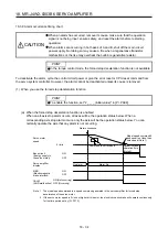
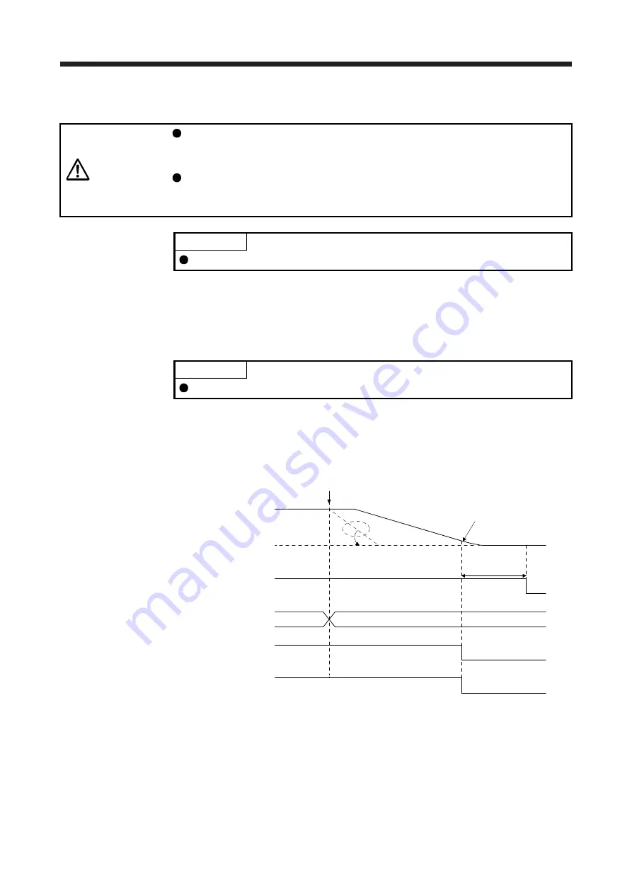
(a) When the forced stop deceleration function is enabled
When an all-axis stop alarm occurs, all axes will be the operation status below. When a
corresponding axis stop alarm occurs, only the axis will be the operation status below. You can
normally operate the axis that any alarm is not occurring.
Command is not received.
Alarm occurrence
Alarm No.
No alarm
Model speed command 0
and equal to or less than
zero speed (Note 1)
MBR
(Electromagnetic
brake interlock)
ON
OFF
ON (Not occurring)
OFF (Occurring)
Base circuit
(Energy supply to
the servo motor)
ON
OFF
Servo amplifier
display
0 r/min
Servo motor
speed
CALM
(AND malfunction)
Dynamic brake
operation time
(Note 2)
Note 1. The model speed command is a speed command generated in the servo amplifier for forced stop
deceleration of the servo motor.
2. If the servo motor speed is 5 r/min or higher at this point, the electric dynamic brake will operate continuously
for the time period set by [Pr. PF12].
Содержание MR-J4W2
Страница 9: ...A 8 MEMO ...
Страница 17: ...8 MEMO ...
Страница 31: ...1 FUNCTIONS AND CONFIGURATION 1 14 MEMO ...
Страница 95: ...4 STARTUP 4 20 MEMO ...
Страница 169: ...6 NORMAL GAIN ADJUSTMENT 6 20 MEMO ...
Страница 201: ...7 SPECIAL ADJUSTMENT FUNCTIONS 7 32 MEMO ...
Страница 213: ...8 TROUBLESHOOTING 8 12 MEMO ...
Страница 219: ...9 OUTLINE DRAWINGS 9 6 MEMO ...
Страница 229: ...10 CHARACTERISTICS 10 10 MEMO ...
Страница 295: ...13 USING STO FUNCTION 13 14 MEMO ...
Страница 327: ...14 USING A LINEAR SERVO MOTOR 14 32 MEMO ...
Страница 371: ...16 FULLY CLOSED LOOP SYSTEM 16 24 MEMO ...
Страница 521: ...APPENDIX App 38 ...
Страница 537: ...MEMO ...
Страница 541: ......


