1. FUNCTIONS AND CONFIGURATION
1 - 3
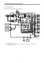
1.2 Function block diagram
The function block diagram of this servo is shown below.
Virtual
encoder
Virtual
motor
B-axis Servo motor
A-axis Servo motor
C-axis Servo motor
Control (A-axis)
U
V
W
U
V
W
U
V
W
Cooling fan
(Note 1)
Built-in
regenerative
resistor
STO circuit
Servo amplifier
or cap
Servo system
controller or
servo amplifier
STO switch
M
E
M
E
M
E
Regenerative
option
CHARGE
lamp
Diode
stack
Relay
Regene-
rative
TR
Current
detector
CNP
1
TRM (A)
CNP2
P+
C
D
MCCB
MC
(Note 2)
Power
supply
Model position
control (A)
Model speed
control (A)
Actual position
control (A)
Actual speed
control (A)
Current
control (A)
CNP
2
Control
circuit
power
supply
Base
amplifier
Overcurrent
(A)
Current
detection
(A)
Overvoltage
I/F
Control
Dynamic
brake circuit (A)
CNP
3A
CN2A
CNP
3B
CN2B
CNP
3C
CN2C
A-axis
output
B-axis
output
C-axis
output
A-axis
F/B
B-axis
F/B
C-axis
F/B
Control (B-axis)
Control (C-axis)
L1
L2
L3
L11
L21
CN8
CN1A
CN1B
+
+
U
U
U
CN5
USB
Personal
computer
Digital I/O
control
MR-BT6VCASE
Battery case +
Battey
(for absolute position
detection system)
Step-down
circuit
CN3
CN4
Note 1. The MR-J4W2-22B has no cooling fan.
2. For 1-phase 200 V AC to 240 V AC, connect the power supply to L1 and L3. Leave L2 open. For the power supply
specifications, refer to section 1.3.
Содержание MR-J4W2
Страница 9: ...A 8 MEMO ...
Страница 17: ...8 MEMO ...
Страница 31: ...1 FUNCTIONS AND CONFIGURATION 1 14 MEMO ...
Страница 95: ...4 STARTUP 4 20 MEMO ...
Страница 169: ...6 NORMAL GAIN ADJUSTMENT 6 20 MEMO ...
Страница 201: ...7 SPECIAL ADJUSTMENT FUNCTIONS 7 32 MEMO ...
Страница 213: ...8 TROUBLESHOOTING 8 12 MEMO ...
Страница 219: ...9 OUTLINE DRAWINGS 9 6 MEMO ...
Страница 229: ...10 CHARACTERISTICS 10 10 MEMO ...
Страница 295: ...13 USING STO FUNCTION 13 14 MEMO ...
Страница 327: ...14 USING A LINEAR SERVO MOTOR 14 32 MEMO ...
Страница 371: ...16 FULLY CLOSED LOOP SYSTEM 16 24 MEMO ...
Страница 521: ...APPENDIX App 38 ...
Страница 537: ...MEMO ...
Страница 541: ......


