17. APPLICATION OF FUNCTIONS
17 - 19
No.
Symbol
Name and function
Initial
value
[unit]
Setting
range
Each/
common
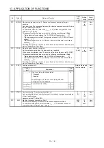
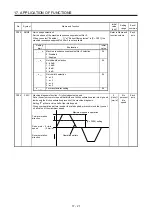
PX11 VRF24B Vibration suppression control 2 - Resonance frequency damping after gain
switching
Set a damping of the resonance frequency for vibration suppression control 2 when
the gain switching is enabled.
To enable this, select "3 inertia mode (_ _ _ 1)" of "Vibration suppression mode
selection" in [Pr. PX02].
This parameter will be enabled only when the following conditions are fulfilled.
"Gain adjustment mode selection" in [Pr. PA08] is "Manual mode (_ _ _ 3)".
"Vibration suppression control 2 tuning mode selection" in [Pr. PX03] is "Manual
setting (_ _ 2 _)".
"Gain switching selection" in [Pr. PB26] is "Control command from controller is
enabled (_ _ _ 1)".
Switching during driving may cause a shock. Be sure to switch them after the servo
motor or linear servo motor stops.
0.00 0.00
to
0.30
Each
axis
PX12
PG1B
Model loop gain after gain switching
Set the model loop gain when the gain switching is enabled.
When you set a value less than 1.0 rad/s, the value will be the same as [Pr. PB07].
This parameter will be enabled only when the following conditions are fulfilled.
"Gain adjustment mode selection" in [Pr. PA08] is "Manual mode (_ _ _ 3)".
"Gain switching selection" in [Pr. PB26] is "Control command from controller is
enabled (_ _ _ 1)".
Switching during driving may cause a shock. Be sure to switch them after the servo
motor or linear servo motor stops.
0.0
[rad/s]
0.0
to
2000.0
Each
axis
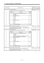
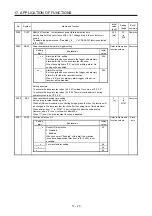
PX13
*XOP2 Function selection X-2
Refer to Name and
function column.
Each
axis
Setting
digit
Explanation
Initial
value
_ _ _ x
One-touch tuning function selection
0: Disabled
1: Enabled
When the digit is "0", the one-touch tuning with MR
Configurator2 will be disabled.
1h
_ _ x _
For manufacturer setting
0h
_ x _ _
0h
x _ _ _
0h
PX14 OTHOV One-touch tuning - Overshoot permissible level
Set a permissible value of overshoot amount for one-touch tuning as a percentage
of the in-position range.
However, setting "0" will be 50%.
0
[%]
0
to
100
Each
axis
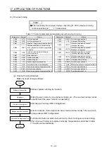
PX17
NH3
Machine resonance suppression filter 3
Set the notch frequency of the machine resonance suppression filter 3.
To enable the setting value, select "Enabled (_ _ _ 1)" of "Machine resonance
suppression filter 3 selection" in [Pr. PX18].
4500
[Hz]
10
to
4500
Each
axis
Содержание MR-J4W2
Страница 9: ...A 8 MEMO ...
Страница 17: ...8 MEMO ...
Страница 31: ...1 FUNCTIONS AND CONFIGURATION 1 14 MEMO ...
Страница 95: ...4 STARTUP 4 20 MEMO ...
Страница 169: ...6 NORMAL GAIN ADJUSTMENT 6 20 MEMO ...
Страница 201: ...7 SPECIAL ADJUSTMENT FUNCTIONS 7 32 MEMO ...
Страница 213: ...8 TROUBLESHOOTING 8 12 MEMO ...
Страница 219: ...9 OUTLINE DRAWINGS 9 6 MEMO ...
Страница 229: ...10 CHARACTERISTICS 10 10 MEMO ...
Страница 295: ...13 USING STO FUNCTION 13 14 MEMO ...
Страница 327: ...14 USING A LINEAR SERVO MOTOR 14 32 MEMO ...
Страница 371: ...16 FULLY CLOSED LOOP SYSTEM 16 24 MEMO ...
Страница 521: ...APPENDIX App 38 ...
Страница 537: ...MEMO ...
Страница 541: ......

