18. MR-J4W2-0303B6 SERVO AMPLIFIER
18 - 43
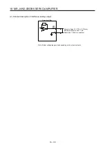
3) The noiseless grounding terminal of the servo motor should be connected to the E1 terminal and
E2 terminal of the servo amplifier.
Servo amplifier
Servo motor
M
E1/E2
4) The encoder of the A axis and B axis servo motors should be connected respectively to the
CN2A and CN2B connectors of the servo amplifier.
(2) I/O signal wiring
(a) The I/O signals should be connected correctly.
Use DO forced output to forcibly turn on/off the pins of the CN3 connector. This function can be used
to perform a wiring check. In this case, switch on the control circuit power supply only.
For details of I/O signal connection, refer to section 18.3.5.
(b) A voltage exceeding 24 V DC is not applied to the pins of the CN3 connector.
(c) Between plate and DOCOM of the CN3 connector should not be shorted.
Servo amplifier
DOCOM
Plate
CN3
18.4.4 Surrounding environment
(1) Cable routing
(a) The wiring cables should not be stressed.
(b) The encoder cable should not be used in excess of its bending life. (Refer to section 10.4)
(c) The connector of the servo motor should not be stressed.
(2) Environment
Signal cables and power cables are not shorted by wire offcuts, metallic dust or the like.
Содержание MR-J4W2
Страница 9: ...A 8 MEMO ...
Страница 17: ...8 MEMO ...
Страница 31: ...1 FUNCTIONS AND CONFIGURATION 1 14 MEMO ...
Страница 95: ...4 STARTUP 4 20 MEMO ...
Страница 169: ...6 NORMAL GAIN ADJUSTMENT 6 20 MEMO ...
Страница 201: ...7 SPECIAL ADJUSTMENT FUNCTIONS 7 32 MEMO ...
Страница 213: ...8 TROUBLESHOOTING 8 12 MEMO ...
Страница 219: ...9 OUTLINE DRAWINGS 9 6 MEMO ...
Страница 229: ...10 CHARACTERISTICS 10 10 MEMO ...
Страница 295: ...13 USING STO FUNCTION 13 14 MEMO ...
Страница 327: ...14 USING A LINEAR SERVO MOTOR 14 32 MEMO ...
Страница 371: ...16 FULLY CLOSED LOOP SYSTEM 16 24 MEMO ...
Страница 521: ...APPENDIX App 38 ...
Страница 537: ...MEMO ...
Страница 541: ......


