17. APPLICATION OF FUNCTIONS
17 - 15
(2) Extension control 2 parameters ([Pr. PX_ _ ])
CAUTION
Never make a drastic adjustment or change to the parameter values as doing so
will make the operation unstable.
If fixed values are written in the digits of a parameter, do not change these values.
Do not change parameters for manufacturer setting.
Do not set a value other than the described values to each parameter.
POINT
The parameter whose symbol is preceded by * is enabled with the following
conditions:
*: After setting the parameter, cycle the power or reset the controller.
**: After setting the parameter, cycle the power.
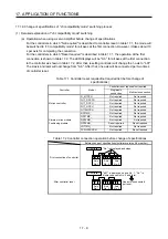
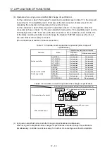
Abbreviations of J3 compatibility mode indicate the followings.
Standard: Standard (semi closed loop system) use of the rotary servo motor
Full.: Fully closed loop system use of the rotary servo motor
Lin.: Linear servo motor use
DD: Direct drive (DD) motor use
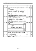
No. Symbol
Name
Initial
value
Unit
Each axis/
Common
J3
compatibility
mode
Standard
F
ull.
Lin.
DD
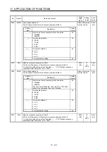
PX01
**J3EX J3 extension function
0000h
Common
PX02
XOP1
Function selection X-1
0000h
Each axis
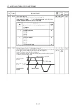
PX03 VRFTX Vibration
suppression control tuning mode (advanced
vibration suppression control II)
0000h Each
axis
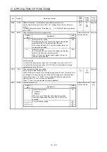
PX04
VRF21 Vibration suppression control 2 - Vibration frequency
100.0
[Hz]
Each axis
PX05
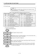
VRF22 Vibration suppression control 2 - Resonance frequency
100.0
[Hz]
Each axis
PX06 VRF23 Vibration
suppression
control 2 - Vibration frequency
damping
0.00
Each
axis
PX07 VRF24 Vibration
suppression control 2 - Resonance frequency
damping
0.00
Each
axis
PX08 VRF21B Vibration suppression control 2 - Vibration frequency after
gain switching
0.0 [Hz]
Each
axis
PX09 VRF22B Vibration
suppression
control 2 - Resonance frequency after
gain switching
0.0 [Hz]
Each
axis
PX10 VRF23B Vibration
suppression control 2 - Vibration frequency
damping after gain switching
0.00
Each
axis
PX11 VRF24B Vibration
suppression control 2 - Resonance frequency
damping after gain switching
0.00
Each
axis
PX12
PG1B
Model loop gain after gain switching
0.0
[rad/s]
Each axis
PX13
*XOP2 Function selection X-2
0001h
Each axis
PX14 OTHOV One-touch tuning - Overshoot permissible level
0
[%]
Each axis
PX15
For manufacturer setting
0000h
PX16
0000h
PX17
NH3
Machine resonance suppression filter 3
4500
[Hz]
Each axis
PX18
NHQ3
Notch shape selection 3
0000h
Each axis
PX19
NH4
Machine resonance suppression filter 4
4500
[Hz]
Each axis
PX20
NHQ4
Notch shape selection 4
0000h
Each axis
PX21
NH5
Machine resonance suppression filter 5
4500
[Hz]
Each axis
Содержание MR-J4W2
Страница 9: ...A 8 MEMO ...
Страница 17: ...8 MEMO ...
Страница 31: ...1 FUNCTIONS AND CONFIGURATION 1 14 MEMO ...
Страница 95: ...4 STARTUP 4 20 MEMO ...
Страница 169: ...6 NORMAL GAIN ADJUSTMENT 6 20 MEMO ...
Страница 201: ...7 SPECIAL ADJUSTMENT FUNCTIONS 7 32 MEMO ...
Страница 213: ...8 TROUBLESHOOTING 8 12 MEMO ...
Страница 219: ...9 OUTLINE DRAWINGS 9 6 MEMO ...
Страница 229: ...10 CHARACTERISTICS 10 10 MEMO ...
Страница 295: ...13 USING STO FUNCTION 13 14 MEMO ...
Страница 327: ...14 USING A LINEAR SERVO MOTOR 14 32 MEMO ...
Страница 371: ...16 FULLY CLOSED LOOP SYSTEM 16 24 MEMO ...
Страница 521: ...APPENDIX App 38 ...
Страница 537: ...MEMO ...
Страница 541: ......


